Adjustment Procedure-2225 Service
g. Set Vertical MODE to CH 2.
h. Repeat Parts b through f for CH 2, using the
Channel 2
XI 0 BAL adjust (R157) instead of R107 in
Part d.
i. Return both VOLTSIDIV Variable controls to their
CAL and
XI positions.
9.
Adjust Attenuator Compensation
a. SET:
VOLTSIDIV (both) 5 mV
Vertical Magnification (both) XI (CAL
knobs in
AC-GND-DC (both) DC
b. Connect the high-amplitude, square-wave
output from the calibration generator via a
504 BNC
termination, a probe-tip-to-BNC adapter, and the
10X probe to the CH 2
OR
Y
input connector.
c. Set the generator to produce a 1-kHz,
five-
division display and compensate the probe using the
probe compensation adjustment (see the probe
instruction manual).
d. Set the CH 2
VOLTSIDIV switch to 10 mV.
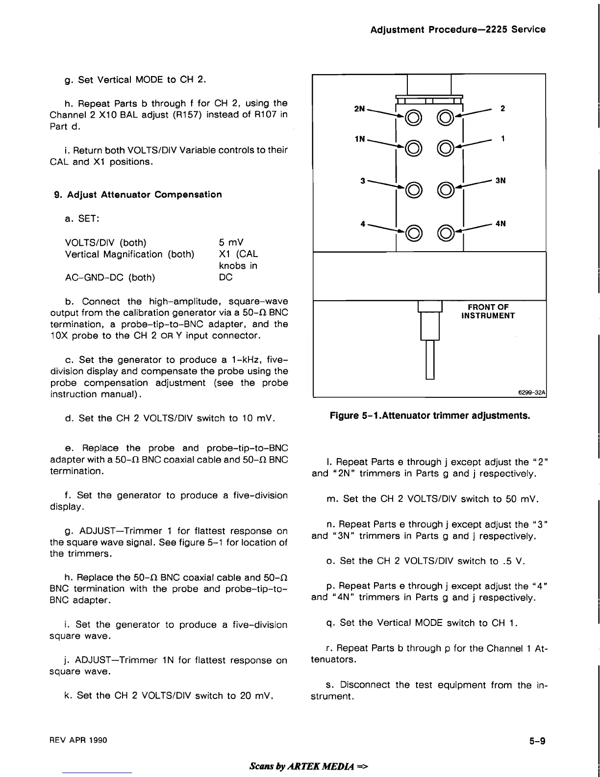
Figure
5-1
.Attenuator trimmer adjustments.
I
FRONT
OF
e. Replace the probe and probe-tip-to-BNC
adapter with a
504 BNC coaxial cable and 504 BNC
I. Repeat Parts e through
j
except adjust the
"2"
termination.
and
"2N" trimmers in Parts g and
j
respectively.
-
f. Set the generator to produce a five-division
display.
INSTRUMENT
m. Set the CH 2 VOLTSIDIV switch to 50 mV.
-
6299-32A
n. Repeat Parts e through j except adjust the
"
3"
g. ADJUST-Trimmer 1 for flattest response on
and
"3N"
trimmers
in
Parts
and
respectively.
the square wave signal. See figure 5-1 for location of
the trimmers.
o. Set the CH 2 VOLTSIDIV switch to
.5 V.
h. Replace the
504 BNC coaxial cable and 504
BNC termination with the probe and probe-tip-to-
p. Repeat Parts e through
j
except adjust the "4"
BNC adapter.
and
"4N" trimmers in Parts g and j respectively.
i.
Set the generator to produce a five-division
q.
Set the Vertical MODE switch to CH 1.
square wave.
r. Repeat Parts b through p for the Channel 1
At-
j. ADJUST-Trimmer 1 N for flattest response on
tenuators.
square wave.
s. Disconnect the test equipment from the in-
k. Set the CH 2
VOLTSIDIV switch to 20 mV.
strument.
REV
APR
1990
scans
by
ARTEK
MEDLQ
=>
 Loading...