Maintenance-2225 Service
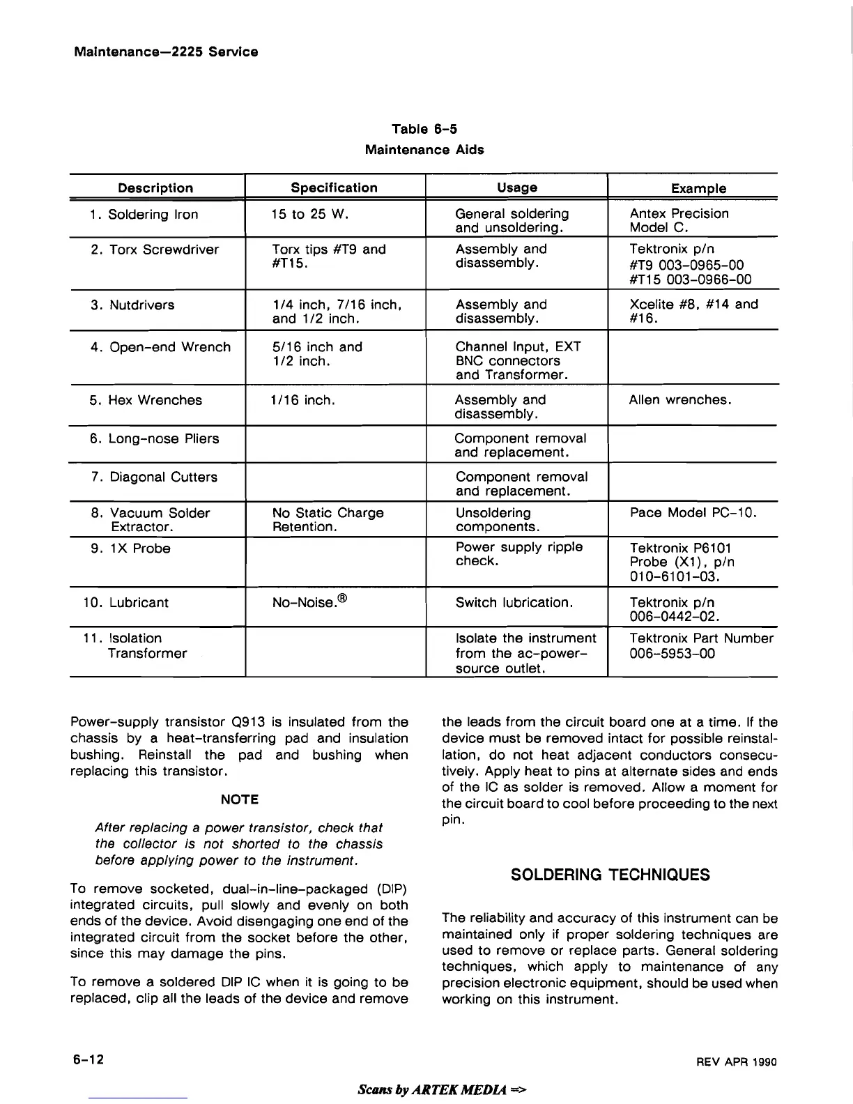
Table
6-5
Maintenance Aids
Power-supply transistor Q913 is insulated from the
chassis by a heat-transferring pad and insulation
bushing. Reinstall the pad and bushing when
replacing this transistor.
NOTE
Example
Antex Precision
Model C.
Tektronix
p/n
#T9 003-0965-00
#TI5 003-0966-00
Xcelite #8, #14 and
#16.
Allen wrenches.
Pace Model PC-1 0.
Tektronix
P6101
Probe (XI
)
,
p/n
01 0-61 01 -03.
Tektronix
p/n
006-0442-02.
Tektronix Part Number
006-5953-00
Description
1. Soldering
Iron
2. Torx Screwdriver
3.
Nutdrivers
4. Open-end Wrench
5. Hex Wrenches
6. Long-nose Pliers
7. Diagonal Cutters
8. Vacuum Solder
Extractor.
9.
1X Probe
10. Lubricant
11
.
Isolation
Transformer
After replacing a power transistor, check that
the collector is not shorted to the chassis
before applying power to the instrument.
To remove socketed, dual-in-line-packaged (DIP)
integrated circuits, pull slowly and evenly on both
ends of the device. Avoid disengaging one end of the
integrated circuit from the socket before the other,
since this may damage the pins.
Specification
15 to 25 W.
Torx tips
#T9 and
#TI
5.
114 inch, 7/16 inch,
and
112 inch.
5/16 inch and
112 inch.
1/16 inch.
No Static Charge
Retention.
NO-~oise.@
To remove a soldered DIP IC when it is going to be
replaced, clip all the leads of the device and remove
Usage
General soldering
and unsoldering
.
Assembly and
disassembly.
Assembly and
disassembly.
Channel Input, EXT
BNC connectors
and Transformer.
Assembly and
disassembly.
Component removal
and replacement.
Component removal
and replacement.
Unsoldering
components.
Power supply ripple
check.
Switch lubrication.
Isolate the instrument
from the
ac-power-
source outlet.
the leads from the circuit board one at a time. If the
device must be removed intact for possible reinstal-
lation,
do not heat adjacent conductors consecu-
tively. Apply heat to pins at alternate sides and ends
of the
IC as solder is removed. Allow a moment for
the circuit board to cool before proceeding to the next
pin.
SOLDERING TECHNIQUES
The reliability and accuracy of this instrument can be
maintained only
if
proper soldering techniques are
used to remove or replace parts. General soldering
techniques, which apply to maintenance of any
precision electronic equipment, should be used when
working on this instrument.
Scans
by
ARTEK
MEW
=>
REV
APR
1990
 Loading...