Sensor and unpowered input connections
Power should never be applied to these terminals. Damage to the control will result.
Connect the two wires from the Outdoor Sensor 070 to terminals
Com Sen — Out Sen
(20 and 22).
Connect the two wires from the Universal Sensor 071 to terminals
Com Sen — Sup Sen
(20 and 21).
Step Two
Mounting the base
The control should be removed from its base by pressing down on the release clip in the wiring chamber and sliding upwards on the
control. The base is then mounted in accordance with the instructions in the Data Brochure D 001.
Step Three
Rough-in Wiring
All electrical wiring terminates in the control base wiring chamber. It has standard 7/8" (22mm) knock-outs that will accept common
wiring hardware and conduit fittings. Before breaking out the knock-outs, check the wiring diagram and select those sections of the
chamber with common voltages, since the safety dividers will later prevent wiring from crossing between sections. Standard 18 to
22 AWG solid wire is recommended for all low voltage wiring to tekmar controls. Heavier guage wire may not fit properly into the
terminal plugs, while lighter guage wire is too fragile and may also contribute too much resistance to the circuit.
Power should not be applied to any of the wires, during this rough-in wiring stage.
•Install the Outdoor Sensor 070, and the Universal Sensor 071 according to the instructions in the Data Brochure D 001 and run the
wiring back to the control.
Options:
A DHW Sensor 071 can be connected. An Indoor Sensor 074, RTU or tekmar Zone Control can
also be connected
(all purchased separately)
. See individual sensor instructions.
•Install the wiring from the other system components; Boiler(s), Pump relays, Heat Demand circuit, etc., to the base.
•Install a 24Vac Class II transformer with a minimum 12VA rating close to the control, and run the wiring from the transformer to the
base.
A Class II transformer must be used. Do not connect any of the transformer terminals to ground, as damage to the control
may result.
5
Maximum 24 Volts
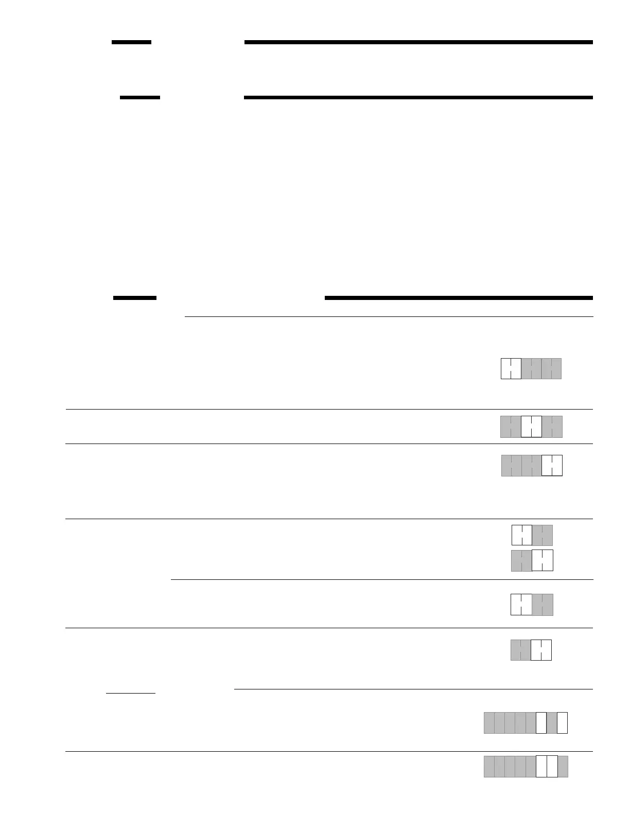
Step Four Electrical connection to the control
Power and output connections
The installer should test to confirm that no voltage is present at any of the wires.
• Install the control into the base, sliding it down until it snaps into place.
• All electrical connections are made directly to the terminal plugs.
• Connect the 24Vac power supply from the secondary side of a 24Vac class II transformer to
terminals
C — R
(5 and 6).
Do not connect either of the transformer terminals to ground.
Connect the System Pump circuit to terminals
System Pmp
(7 and 8). These terminals lead to a dry
relay contact which closes when the control requires System Pump operation.
If a DHW pump or valve is to be operated by the control, connect its circuit to terminals
DHW Pmp
(9
and 10). These terminals lead to a dry relay contact which closes when the control requires DHW pump
/ valve operation.
Note:
The 252 is approved for low voltage only (maximum 24Vac). Line voltages to the pump(s)
must be switched through isolation relay(s).
Connect the boiler circuit(s) to terminals
Stage 1
(11 and 12) and
Stage 2
(13 and 14). Each set of
terminals lead to a dry relay contact which closes when the control requires boiler operation. Boilers
with a 24Vac control circuit can be switched directly through the control. If higher voltages are used,
isolation relays must be installed.
Powered input connections
If a 24Vac external Heat Demand signal is used, (zone valve end switches, etc.) connect the wiring
from the Heat Demand circuit to terminals
Heat Dem — Heat Dem
(1 and 2). When 24Vac is applied
to these terminals, the control will recognize a "call for heat" from the system.
If no DHW Sensor is installed, but a 24Vac DHW Demand signal from an aquastat is used,
connect
the wiring from the DHW Demand circuit to terminals
DHW Dem — DHW Dem
(3 and 4).
When 24Vac
is applied to these terminals, the control will recognize a "call for Domestic Hot Water" and switch into
DHW mode.
910
PmpPmp
DHW
65
C R
Power
78
PmpPmp
System
65
C R
Power
78
PmpPmp
System
910
PmpPmp
DHW
1234
Dem DemDemDem
Heat
DHW
1234
Dem DemDemDem
Heat
DHW
910
78
PmpPmp
PmpPmp
System DHW
65
C R
Power
12 13 1411
1 1 22
Stage
Stage
12 13 1411
1 1 22
Stage
Stage
18
UnO
Sw
16
DHW
Sen
21
Sup
Sen
19
10K
Sen
15
2K
RTU
17
Com
Sen
20
Com
Sen
Out
Sen
22
16
DHW
Sen
Out
Sen
2219
10K
Sen
15
2K
RTU
17
Com
Sen
18
UnO
Sw
21
Sup
Sen
20
Com
Sen
 Loading...