© 2010 D 132 - 04/10 2 of 12
How To Use The Data Brochure
Settings ............................................................Pg 8
Testing the Control .........................................Pg 9
Error Messages ...............................................Pg 10
Technical Data .................................................Pg 12
Limited Warranty ............................................Pg 12
Sequence of Operation ..................................Pg 2
Section A: General Operation ..............Pg 2
Section B: Pump Operation ..................Pg 3
Section C: Alert Operation ...................Pg 4
Installation .......................................................Pg 5
This brochure is organized into three main sections. They are: 1) Sequence of Operation, 2) Installation, 3) Troubleshooting. The
Sequence of Operation section has three sub-sections. We recommend reading Section A: General Operation of the Sequence of
Operation, as this contains important information on the overall operation of the control. Then read the sub-sections that apply to your
installation.
Table of Contents
Section A
General Operation
Page 2 - 3
Section B
Pump Operation
Page 3 - 4
Section C
Alert Operation
Page 4
Sequence of Operation
Section A: General Operation
POWERING UP THE CONTROL
-----------------------------------------------------------------------------------------------------------------
-----------------------------------------------------------------------------------------------------------------
When the Pump Sequencer 132 is powered up, a software version code is displayed for 2 seconds, then the control turns on all
of the red LED’s for 2 seconds. After this test, the control enters its normal operating mode. When the control is powered up, the
Power light remains on continuously.
OPERATION
--------------------------------------------------------------------------------------------------------------------------------------------
--------------------------------------------------------------------------------------------------------------------------------------------
The Pump Sequencer 132 has two modes of operation. The 132 is capable of operating two pumps in either a stand-by or 2-stage
configuration.
Stand-by
----------------------------------------------------------------------------------------------------------------
In the stand-by mode of operation the 132 automatically switches over from the lead pump to the stand-by pump if the lead pump
fails to provide flow in the system.
2-Stage
-----------------------------------------------------------------------------------------------------------------
In the 2-stage mode of operation the 132 turns on the second stage pump if there is a requirement for additional flow in the
system. At the same time the control still provides stand-by pump operation.
PUMP DEMAND
--------------------------------------------------------------------------------------
--------------------------------------------------------------------------------------
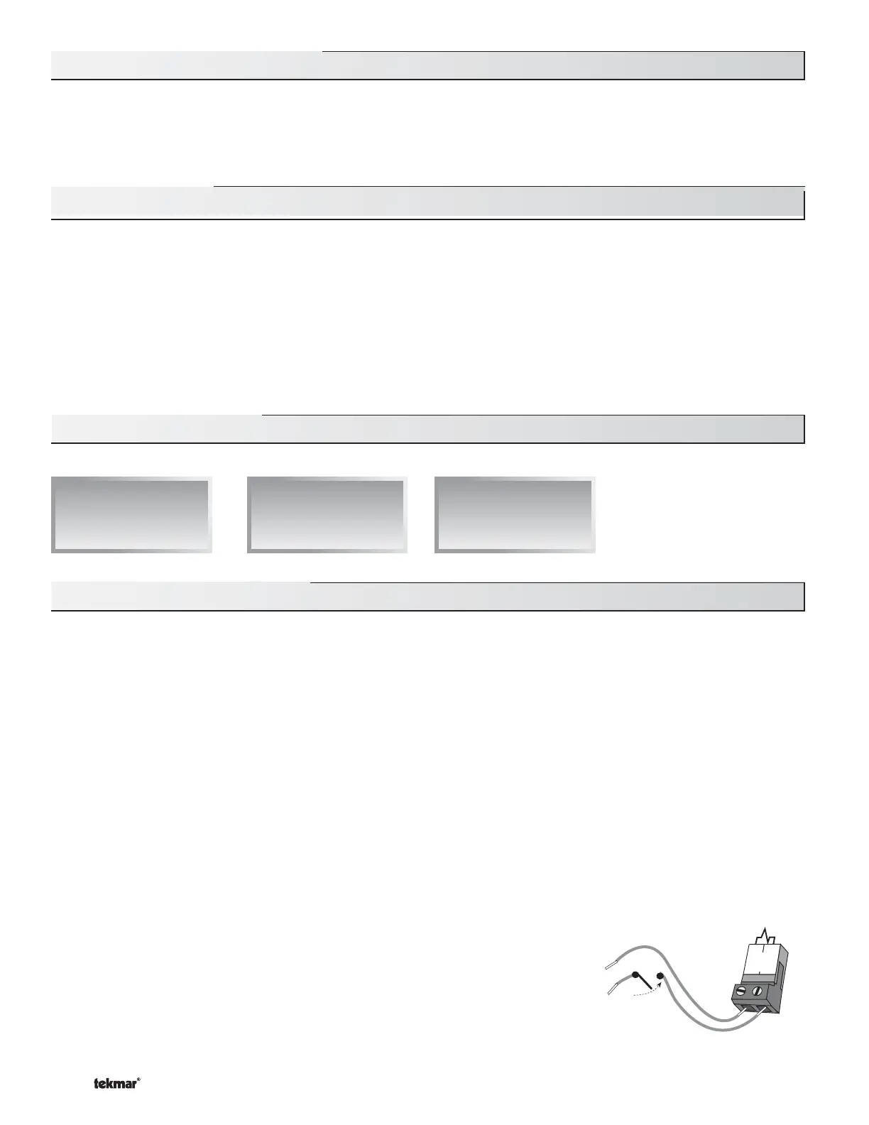
A pump demand is required in order for the 132 to provide flow. A pump demand is gener-
ated by applying a voltage between 24 and 240 V (ac) across the Pump Demand terminals
(1 and 2). Once voltage is applied, the Pump Demand light is turned on and the pump(s)
operate as required. A pump demand can be permanently powered, or generated from an
external source such as a manual switch or another control system.
1
2
Pump
Demand
24 to 240 V (ac)
 Loading...