Do you have a question about the Teknim TFP-121 Series and is the answer not in the manual?
Details the capabilities and features of the TFP-121x series system.
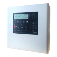
Explains the indicators, buttons, and their functions on the control panel.
Specifies recommended cable types and properties for wiring installations.
Step-by-step guide for physically mounting and installing the panel.
Details the requirements and connection for the panel's main power supply.
Instructions for connecting the backup batteries to the panel.
Procedure to activate the internal watch battery for clock functionality.
Describes the panel's input and output terminals and their functions.
Guide for connecting additional loop expansion cards to increase loop capacity.
Discusses the architecture and capabilities of the loop lines in the system.
Explains the Class A loop connection method and monitoring.
Explains the Class B loop connection method and its limitations.
Steps for installing and activating a network card for system networking.
Details how to connect a repeater panel to the main system.
Outlines the process for activating the fire detection system panel.
Defines the different user access levels and their associated authorizations.
Details configuration via computer, including TCP/IP settings.
Procedure for accessing Level-3 for system configuration.
Setting the panel's clock and date for accurate event logging.
Configures essential panel parameters like address, mode, and language.
Configures general delay times for system responses.
Configures specific delay times for individual zones.
Procedure for adding newly connected devices to the system.
Configures parameters for individual devices such as zone, label, and sensitivity.
Configures zone-specific parameters like labels for better identification.
Overview of messages for "Fire", "Error", and "Warning" status.
Detailed view of fire events with sequence, label, and zone information.
Lists system errors, their causes, and affected components.
Informs about non-critical situations affecting system functions.
Records and displays categorized system events for analysis.
Allows disabling devices, zones, siren outputs, and loop lines.
Tests alarm functions of fire detection devices within specific zones.
Checks device addressing and communication health via LED indicators.
Provides contact information for technical support and service personnel.
Tracks the total number of alarm states since initial installation.
Displays key panel operational data like voltages, temperatures, and versions.
Manages loop-related operations, including device lists, control, and information.
Lists devices included in the loop for display purposes.
Determines the location of discontinuities within the loop line.
Provides status information related to loop input/output voltages and current.
Procedure for adding newly addressed and connected devices to the system.
Procedure for removing a device from the loop after it has been physically removed.
Configures loop parameters such as label, connection type, and activation status.
Manages network communication and parameters using the TdNET protocol.
Lists and manages control panels visible on the network.
Configures network mode, event logging, time sync, and other TdNET settings.
Sets how the panel evaluates commands received from other network panels.
Configures commands the panel transmits to the network.
Manages user accounts, levels, and passwords for panel access.
Configures and manages service reminders for panel maintenance.
Describes user-level maintenance tasks and error diagnostics.
Troubleshoots errors related to open circuits in loop lines.
Diagnoses and resolves errors when a device is not detected on the loop.
Outlines daily, weekly, and quadrennial inspection procedures for the system.
Provides mechanical diagrams and details for panel installation.
Details electrical connections, battery, and sounder wiring.
Illustrates menu flows for different user levels and system functions.
Explains how to connect the panel to a computer for configuration.
Details compliance with EN 54 standards and optional functions.
Provides a table format for recording maintenance activities.
Guidelines for consumer maintenance, repair, and cleaning procedures.
Warnings against unauthorized operation and settings modification.
Precautions for careful handling and transportation to prevent damage.
| Display Type | LCD |
|---|---|
| IP Rating | IP30 |
| Battery Voltage | 12V DC |
| Fire Relay Output | 1A |
| Fault Relay Output | 1A |
| Approval | EN54 |
| Mounting | Wall Mount |
| Communication Ports | RS-485 |