Directional
marks
BEND LAYOUT EXAMPLE
page 2
45˚
5"
5"
Reference
mark
Vertex
Vertex
FIG. 1
5"
Reference
mark
Bend
mark
FIG. 1B
FIG. 2
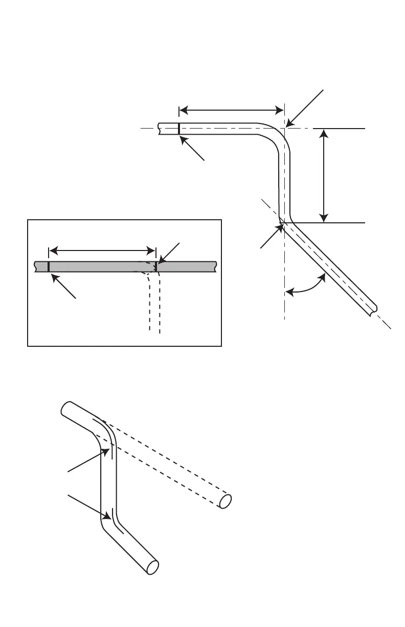
To measure tubing for
bending, use the center line
of the tubing as shown.
When establishing first
measurement, make a
REFERENCE mark for the
starting point of
measurement. In the
example shown, a distance
of 5" is desired between
reference mark and 90˚
bend. Make a BEND mark at
5". Proceed to page 2 for
bending procedure.
To make sure bends are made along
the desired axis, mark the centerline
on tubing before bending.