EasyManuals Logo
Home>Tektronix>Pulse Generator>114

Tektronix 114 User Manual

Tektronix 114
50 pages
To Next Page IconTo Next Page
To Previous Page IconTo Previous Page
Page #5 background imageLoading...
Page #5 background image
SECTION
1
CHARACTERISTICS
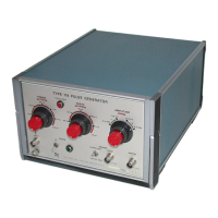
Introduction
The
Type
114
Pulse
Generator
is
a
general
purpose
pulse
generator.
Transistorized
circuitry
is
used
throughout,
with
most
of
the
components
being
mounted
on
an
etched
circuit
board.
The
Type
114
Pulse
Generator
is
versatile.
The
repetition
rate,
width,
and
amplitude
of
the
output
pulse
are
individual
ly
selectable
by
range
and
by
variable
control
within
each
range.
Front-panel
connectors
are
provided
for
the
pulse
out
put,
trigger
output,
and
external
trigger
input.
A
single
front
panel
switch
selects
both
the
amplitude
range
and
polarity
of
the
output
pulse.
The
trigger
output
pulse
is
set
by
a
front
panel
switch
to
occur
on
the
desired
edge
(leading
or
trailing)
of
the
output
pulse.
In
cases
where
the
Type
114
is
set
for
a
pulse
width
longer
than
the
pulse
repetition
period,
a
built-
in
feature
automatically
counts
down
the
repetition
rate
to
permit
the
width
of
the
output
pulse
to
remain
at
the
value
selected
(such
operation
is
indicated
by
a
Width
>
Period
light).
In
addition,
two
Type
114's
can
be
connected
together
so
that
the
output
pulse
of
the
second
unit
is
delayed
by
the
pulse
width
(up
to
10
ms)
of
the
first
unit.
short
circuiting
the
OUTPUT
connector
will
not
damage
the
instrument.
WARNING
The
Type
114
should
never
be
connected
to
an
inductive
load,
or
any
load
that
will
produce
a
current
which
will
feed
back
into
the
instrument.
TABLE
1-1
Amplitude
Range
Pulse
on
Pulse
off
±1
to
3
V
20
19
to
22
±3
to
10
V
28
to
48
30
to
95
Electrical
Pulse
Period.
The
PERIOD
switch
and
associated
VARI
ABLE
control
provide
continuously
variable
pulse
periods
from
1
µ
sec
to
100
msec
(pulse
repetition
rates
from
one
mil
lion
pulses
per
second
to
10
pulses
per
second).
An
EXTER
NAL
TRIGGER
position
on
the
PERIOD
switch
permits
exter
nal
control
of
the
pulse
period.
With
the
VARIABLE
control
at
the
CAL
end
of
its
range
and
the
WIDTH
>
PERIOD
light
unlit,
the
period
accuracy
is
within
±3%
of
the
indicated
value.
Jitter
is
typically
less
than
0.05%
of
pulse
period
+2
ms.
Pulse
Width.
The
WIDTH
switch
and
associated
VARI
ABLE
control
provide
continuously
variable
pulse
widths
from
l
00 n
sec
to
10
msec.
With
the
width
VARIABLE
control
at
the
CAL
end
of
its
range,
the
width
accuracy
is
within
±3%
of
indicated
value.
Jitter
is
typically
less
than
0.05%
plus
½
nsec.
An
additional
SQUARE
WAVE
position
on
the
WIDTH
switch
disables
the
variable
width
feature
and
changes
the
output
to
a
square
wave
whose
repetition
rate
is
determined
by
the
PERIOD
controls.
Period
error
in
the
square
wave
mode
is
<
±5%.
Output
Polarity
and
Amplitude.
The
AMPLITUDE
switch
provides
for
either
polarity
output
with
two
amplitude
ranges
(1
V
to
3
V
and
3
V
to
10
V).
The
VARIABLE
control
permits
the
output
to
be
varied
within
the
voltage
ranges.
Aber
rations
(overshoot,
rolloff,
preshoot,
or
ringing)
amount
to
less
than
5%
at
maximum
amplitude.
Output
Impedance.
The
output
impedance
of
the
Type
114
is
given
in
Table
1-1.
The
figures
given
are
typical
and
are
dependent
upon
the
setting
of
the
AMPLITUDE
VARI
ABLE
control.
Load
impedance
is
not
critical.
Temporarily
External
Trigger
Input.
External
triggering
requires
a
positive
trigger
signal
of
2
to
20
volts
and
having
a
risetime
of
1
µ
sec
or
less.
Triggering
signals
up
to
2
Mc
may
be
used.
Trigger
Output.
The
trigger
output
pulse
into
an
open
circuit
is
approximately
3
volts;
into
a
50
termination,
the
trigger
output
pulse
is
approximately
'/
2
volt.
A
front-panel
switch
allows
the
output
trigger
pulse
to
be
set
to
occur
at
the
leading
edge
or
the
trailing
edge
of
the
main
pulse.
Input
Power
Requirements.
15
watts;
50
to
400
cps,
94.5
to
137.5
or
189
to
275
volts,
ac.
Warm-up
Time
at
+25°C
±5°C.
Five
minutes
for
rated
accuracies.
Environmental
Operating
Temperature
Altitude
Non-Operating
Temperature
Altitude
Mechanical
Dimensions
Connectors
Accessories
0°C
to
+50°C
15,000
feet
maximum
40°C
to
+65°C
50,000
feet
maximum
Approximately
9"
X
6"
X
12
½"
overall
Front-panel
connectors
are
BNC
type.
See
standard
accessory
lists
in
this
manual
for
accessories
supplied
with
each
instrument.
For
optional
accessories,
see
the
current
Tektronix,
Inc.
catalog.
1-1

Questions and Answers:

Question and Answer IconNeed help?

Do you have a question about the Tektronix 114 and is the answer not in the manual?

Tektronix 114 Specifications

General IconGeneral
BrandTektronix
Model114
CategoryPulse Generator
LanguageEnglish

Related product manuals