Operating
Instructions—
51
03N
r
r
f
Vertical
distance
1
I
1
—
—
—
'
"
(A)
—
—
J
A
Reference
line
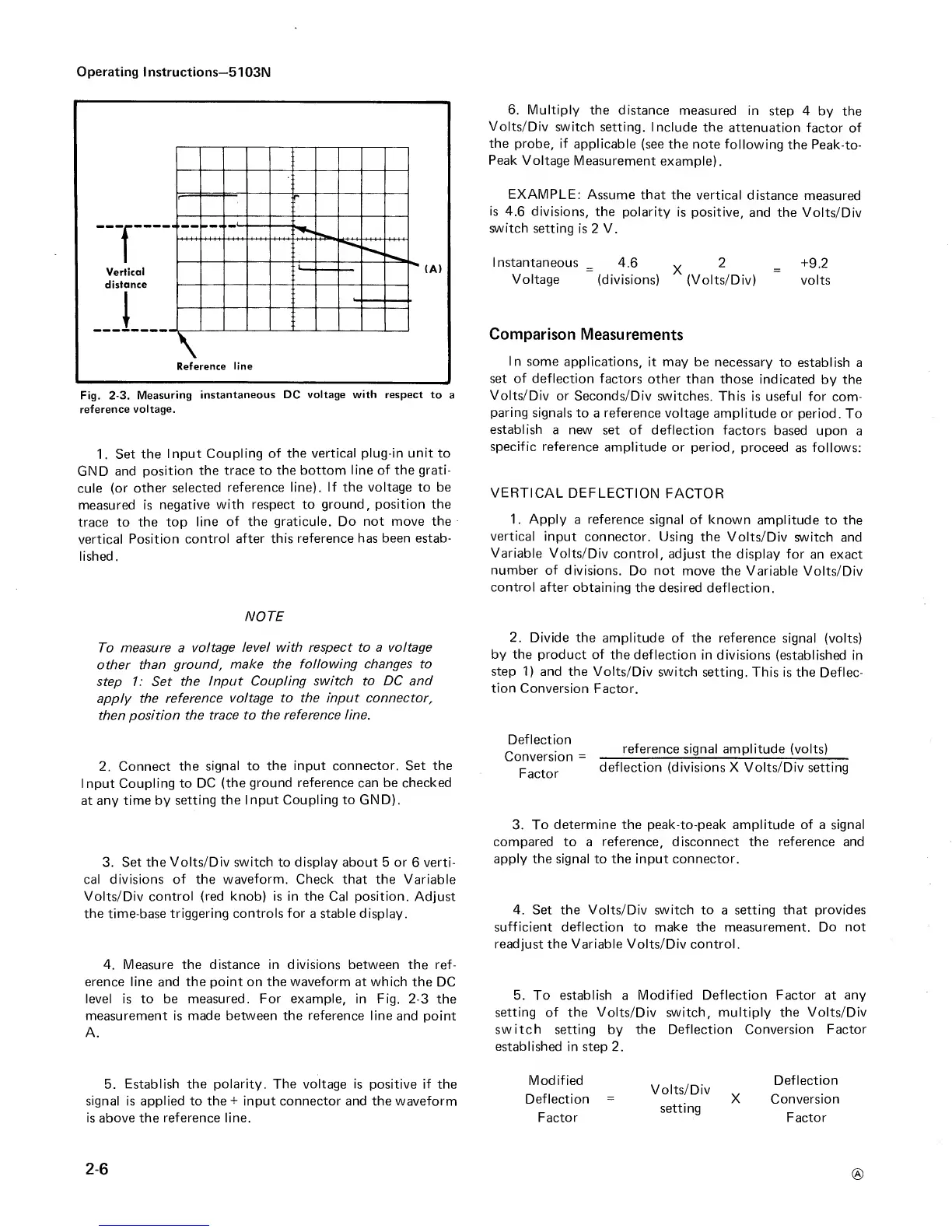
Fig.
2-3. Measuring
instantaneous DC
voltage with
respect to
a
reference
voltage.
1.
Set the
Input
Coupling
of the vertical
plug-in unit
to
GND and
position
the
trace to the bottom
line of the grati-
cule
(or other
selected
reference
line).
If the voltage to be
measured is
negative
with
respect to ground, position
the
trace to the
top
line
of the graticule. Do not move
the
vertical
Position
control
after this
reference has been estab-
lished.
6. Multiply
the distance
measured
in
step 4 by the
Volts/Div
switch setting.
Include the
attenuation
factor of
the probe, if
applicable
(see the
note following
the Peak-to-
Peak
Voltage
Measurement
example).
EXAMPLE:
Assume that
the vertical
distance
measured
is
4.6
divisions,
the polarity
is positive,
and
the Volts/Div
switch
setting
is 2
V.
Instantaneous
_ 4.6
^
2
-
+9.2
Voltage
(divisions) (Volts/Div)
volts
Comparison
Measurements
In
some
applications,
it
may
be necessary
to establish
a
set
of
deflection
factors other
than those
indicated
by the
Volts/Div or
Seconds/Div switches.
This
is useful for
com-
paring
signals to
a
reference
voltage
amplitude or
period. To
establish
a new set of
deflection
factors based
upon
a
specific reference
amplitude or period,
proceed
as
follows:
VERTICAL
DEFLECTION
FACTOR
1.
Apply
a
reference
signal of known
amplitude
to the
vertical
input
connector. Using the
Volts/Div
switch and
Variable
Volts/Div
control, adjust the
display for
an exact
number of
divisions.
Do not
move the Variable
Volts/Div
control after
obtaining the
desired deflection.
NOTE
To
measure
a
voltage level with respect to a voltage
other
than
ground,
make the following changes to
step 1: Set
the
Input Coupling
switch to
DC
and
apply the
reference
voltage to the input connector,
then
position the
trace to the
reference line.
2.
Connect
the
signal to
the input connector. Set the
Input
Coupling to
DC
(the ground reference can be checked
at
any time by
setting the
Input Coupling to GND).
3.
Set the
Volts/Div switch
to
display
about 5 or
6
verti-
cal divisions
of
the
waveform. Check
that the Variable
Volts/Div control
(red
knob) is in the Cal position.
Adjust
the time-base triggering
controls for
a stable display.
4.
Measure the distance in divisions between the ref-
erence line and the point on the
waveform
at which the
DC
level is to be
measured. For example,
in Fig.
2-3
the
measurement is made
between
the reference line
and point
A.
5.
Establish the polarity. The voltage is
positive
if
the
signal
is
applied
to the
+
input connector and the waveform
is above the reference line.
2.
Divide the amplitude of
the reference
signal (volts)
by the
product
of
the
deflection in
divisions (established
in
step
1)
and the
Volts/Div
switch
setting. This is the Deflec-
tion
Conversion
Factor.
Deflection
Conversion
=
Factor
reference signal amplitude (volts)
deflection (divisions X Volts/Div setting
3.
To determine the peak-to-peak amplitude
of
a signal
compared
to a
reference,
disconnect the
reference and
apply the
signal to the input
connector.
4.
Set the
Volts/Div switch to
a setting
that provides
sufficient deflection
to
make the measurement. Do not
readjust the Variable Volts/Div control.
5.
To establish
a
Modified Deflection Factor
at
any
setting of the Volts/Div switch, multiply the Volts/Div
switch
setting by
the Deflection Conversion Factor
established
in step 2.
Modified
Deflection
Factor
Volts/Div
setting
Deflection
Conversion
Factor
®
2-6
 Loading...


