Brief procedures
4. Click the Home tabonthedisplay.
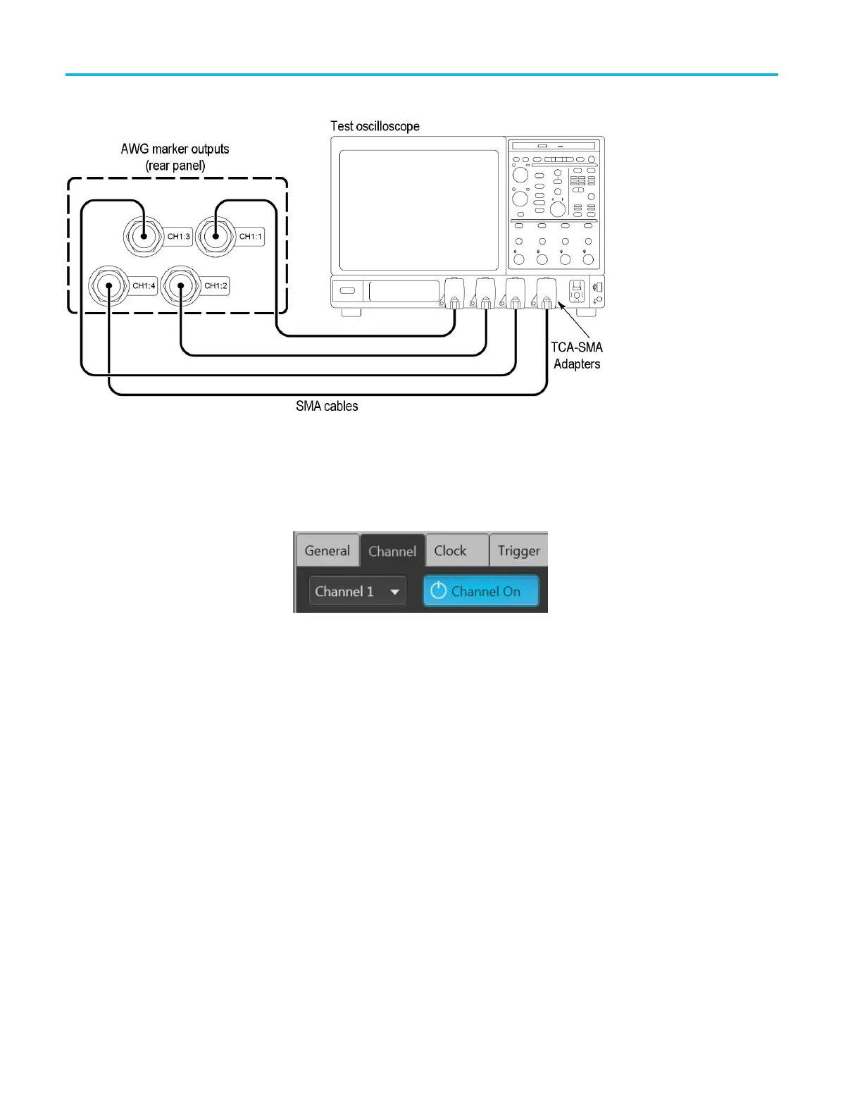
5. From the W
aveform List window, assign the waveform PV_Square.wfmx
to Channel 1.
6. Click th
e Setup -> Channel tab and enable the select Channel 1 output.
7. In the Setup -> Channel tab, select Output Settings and set the Channel 1
Resol
ution to 12+4 Mkrs.
8. Click the Play button on-screen or on the f ront panel.
9. Press the AWG front panel All Outputs Off button (or click All Outputs Off
on the Home screen) to enable the outputs (front panel light off).
10. Check that the CH1:1 through CH1:4 waveforms are properly displayed on
the test oscilloscope screen.
34 AWG5200 Series Technical Reference

 Loading...


