Brief procedures
8. Click the Reset to Default Setup button in the toolbar .
9. Set the Function Generator to output a 1 kHz square wave at 5 V
p-p
.
10. Turn on the output of the Function Generator.
11. Load the test waveform PV_Square.wfmx into the Waveform List.
Test wavefo
rms are located at C:\Program
Files\Tektronix\AWG5200\Samples\PV.
12. From the Wa
veform List window, assign the w aveform PV_Square.wfmx
to Channel 1.
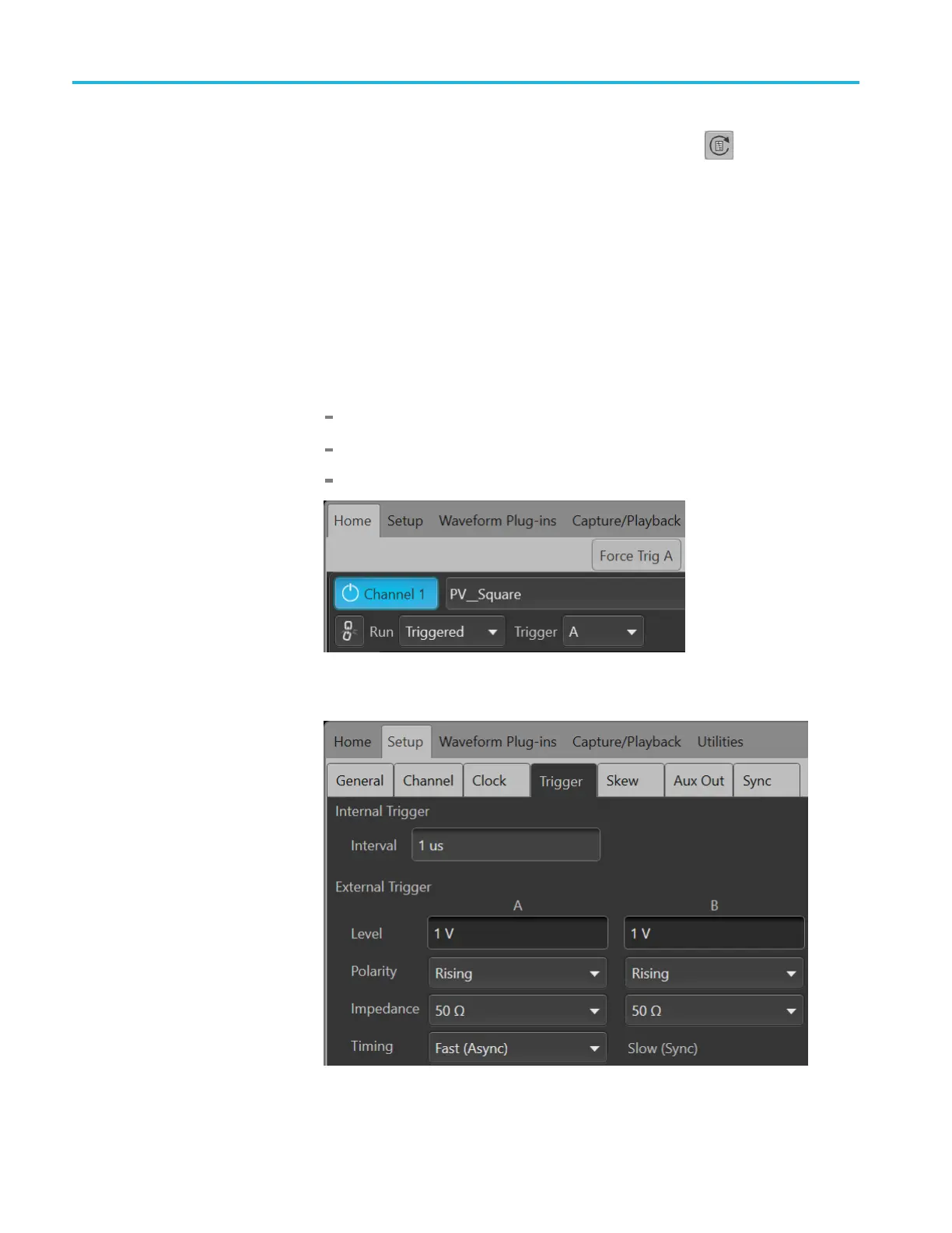
13. Click the
Home tab and set the AWG’s Channel 1 as follows:
Run Mode to Triggered
Trigger Input to A
Enable the Channel
14. In the Setup -> Trigger tab, set the External Trigger Level to 1.0 V (A and
B). Leave all other settings to their default settings.
40 AWG5200 Series Technical Reference

 Loading...


