Performance tests
Before startin
g this procedure, ensure you have the “Term R” value used in the
calculations. (See page 44, Termination resistance measurement.)
1. Click the Reset to Default Setup button in the toolbar
.
2. Press the AWG front panel All Outputs Off button (or click All Outputs Off
on the Home screen) to disable the outputs (front panel light on).
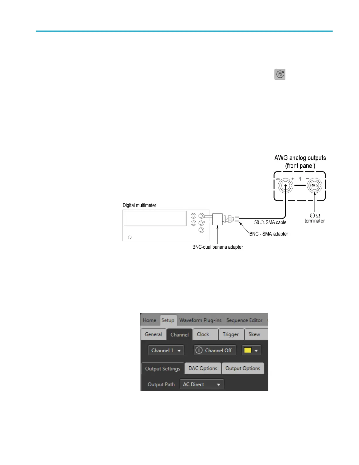
3. Connect the CH 1 (+) connector from the AWG to the HI and LO inputs of
the digital multimeter. Use a 50 Ω SMA cable, a BNC-SMA adapter, and
a BNC dual banana adapter.
4. Terminate the CH 1 (–) connector on the AWG using a 50 Ω SMA terminator.
5. Press the AWG front panel All Outputs Off button (or click All Outputs Off
on the Home screen) to enable the outputs (front panel light off).
6. Click the Setup -> Channel tab and click the Output Settings tab.
a. Select Channel 1.
b. Set the Output Path to AC Direct.
c. Enable the Channel 1 output.
AWG5200 Series Technical Reference 55

 Loading...


