Do you have a question about the Tektronix Sony 370A and is the answer not in the manual?
Description of safety symbols and warnings indicated on the equipment.
Definitions for cautionary and warning statements used within the operator manual.
Explanation of the meaning of symbols used in the manual for cautionary information.
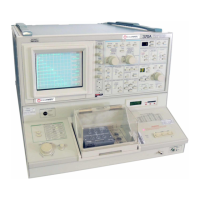
Overview of the 370A as a microprocessor-controlled semiconductor curve tracer.
Detailed instructions on how to install the 370A instrument.
Procedures for performing an initial inspection of the instrument before operation.
Information regarding the instrument's power source requirements and specifications.
Specifies the ambient temperature range for safe and effective instrument operation.
Information on using test adapters and the importance of the protective cover for safe operation.
Instructions and considerations for mounting the 370A instrument in a standard rack.
Guidelines and procedures for properly repackaging the instrument for shipping.
Detailed technical specifications and performance requirements for the 370A instrument.
Explanation of the Kelvin sense measurement method for high-precision voltage measurement.
Overview of the section covering the instrument's controls, indicators, and connectors.
Detailed explanation of instrument power controls and CRT (display) controls.
Description of measurement modes, acquisition modes, and magnification controls.
Explanation of controls for managing memory index and instrument setups.
Details on controls used to adjust and configure the instrument's display.
Information on using cursor controls for precise measurement and position adjustments.
Guide to operating the step generator for creating voltage and current steps.
Explanation of controls for setting the collector supply voltage and current.
A general description of how the 370A operates and its measurement capabilities.
Step-by-step guide for the initial operation and setup of the instrument.
Introduction to the General Purpose Interface Bus (GPIB) and its role with the instrument.
Description of the hardware components that constitute the GPIB interface circuits.
Explanation of the communication protocol used for GPIB interfacing.
Details on interface messages, including commands and responses, for GPIB communication.
List of available optional accessories and power cords for the 370A instrument.
Explanation of the instrument's diagnostic routines and their functions.
Description of the diagnostic routines automatically performed by the instrument upon power-on.
Procedure for initiating a diagnostic routine manually by the user.
| Brand | Tektronix |
|---|---|
| Model | Sony 370A |
| Category | Laboratory Equipment |
| Language | English |