Triggering on Waveforms
3–54
TDS 500B, TDS 600B, & TDS 700A User Manual
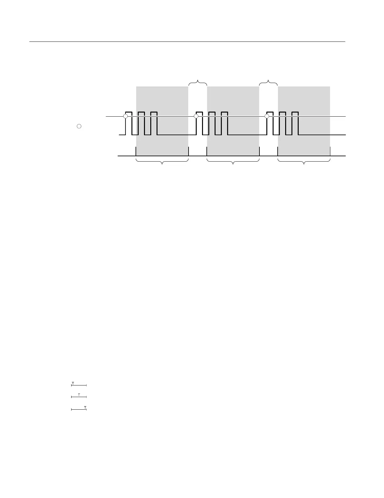
Holdoff Holdoff
Indicates
Trigger Points
Trigger Level
Holdoff
Acquisition
Interval
Acquisition
Interval
Triggers are not recognized during holdoff time.
Figure 3–31: Trigger Holdoff Time Ensures Valid Triggering
Holdoff is settable from 250 ns (minimum holdoff available) to 12 seconds
(maximum holdoff available). To see how to set holdoff, see To Set Mode &
Holdoff on page 3–61.
You can also set a default holdoff. The default hold is the “general purpose”
holdoff for most triggering signals and varies with the horizontal scale. It is
equal to 5 divisions times the current time/division settings.
Trigger coupling determines what part of the signal is passed to the trigger
circuit. All trigger types except edge triggering use only DC coupling; edge
triggering can use all available coupling types: AC, DC, Low Frequency
Rejection, High Frequency Rejection, and Noise Rejection: See To Specify
Coupling on page 3–60 for a description of each coupling mode.
The adjustable feature trigger position defines where on the waveform record the
trigger occurs. It lets you properly align and measure data within records. The
part of the record that occurs before the trigger is the pretrigger portion. The part
that occurs after the trigger is the posttrigger portion.
To help you visualize the trigger position setting, the top part of the display has
an icon indicating where the trigger occurs in the waveform record. You select in
the Horizontal menu what percentage of the waveform record will contain
pretrigger information.
Displaying pretrigger information can be valuable when troubleshooting. For
example, if you are trying to find the cause of an unwanted glitch in your test
circuit, it might trigger on the glitch and make the pretrigger period large enough
Trigger Coupling
Trigger Position
 Loading...


