Triggering on Waveforms
3–58
TDS 500B, TDS 600B, & TDS 700A User Manual
Main Time Base
Main Time Base Time/Div
Main Trigger
Source = Ch 1
Main Trigger
Slope = Rising Edge
Main Trigger
Level
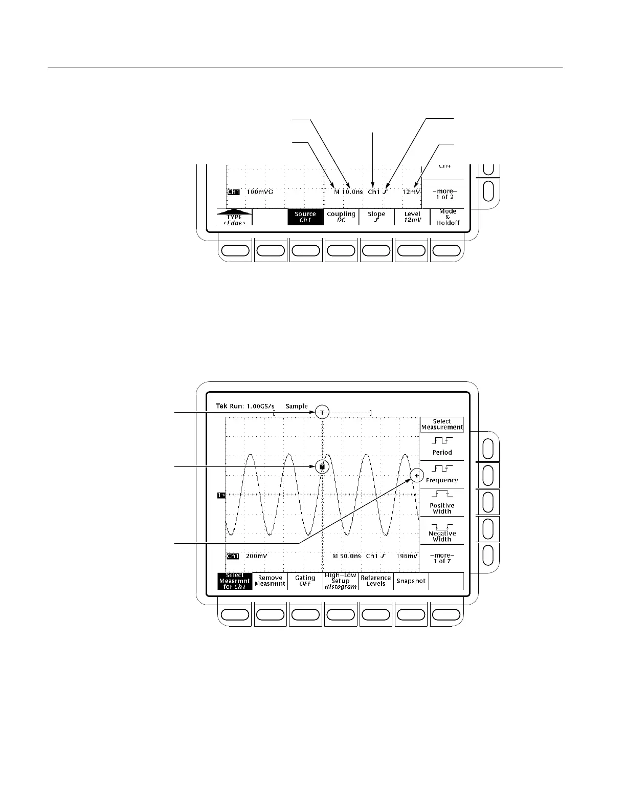
Figure 3–34: Example Trigger Readouts — Edge Trigger Selected
Record View. To determine where the trigger point is located in the waveform
record and with respect to the display, check the record view at the top of the
display. (See Figure 3–35.)
Trigger Position Relative to the
Display and Waveform Record
Trigger Point Indicator
Indicating the Trigger Position
on the Waveform Record
Trigger Bar Indicating the Trigger
Level on the Waveform Record
Figure 3–35: Record View, Trigger Position, and Trigger Level Bar Readouts
Trigger Position and Level Indicators. To see the trigger point and level on the
waveform display, check the graphic indicators Trigger Position and Trigger Bar.
Figure 3–35 shows the trigger point indicator and trigger level bar.
 Loading...


