GB
39
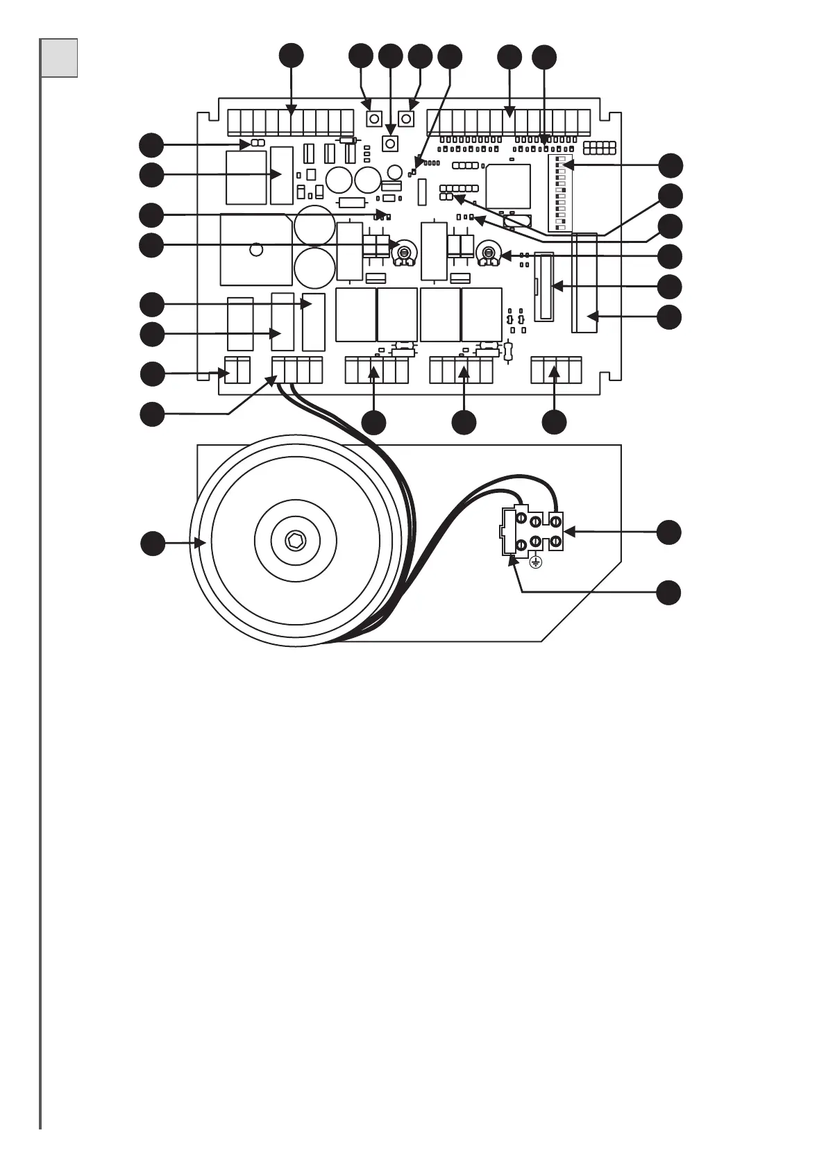
PART DESCRIPTION (Fig. 11)
1 Fuse for 230V line T2A (5x20 slow-acting)
2 Terminal board for connection of 230V power line
3 Transformer
4 Terminal board for connection of transformer secondary winding and battery charger (optional)
5 Terminal board for connection of courtesy light (N.O. contact)
6 Low voltage fuse for 24V F16A (5x20)
7 Battery/battery charger fuse 24V T10A (5x20 slow-acting)
8 Trimmer 1 to set speed
9-21 Motor operation leds (LD1 and LD2)
10 Auxiliary fuse 24V F5A (5x20)
11 Photocell Test (see chapter PHOTO-TEST)
12 Terminal board for connection of: auxiliary power supply, gate open indicator and electric lock.
13 Pushbutton for Programming and Stop*.
14 Pushbutton P3 (Pause time programming)
15 Step-by-Step pushbutton (S/S)
16 Programming Led (LD3)
17 Terminal board for connection of controls and safety devices
18 Indicator leds for control input status. Led on = input closed; led off = input open
19 Function Dip-switches
20 Control unit Reset (short the 2 pins briefly to cut off and restore power on the control unit)
22 Trimmer 2 to set deceleration rate
24 Connector for insertion of board type receiver (optional)
25 Terminal board for connection of aerial and second channel of radio receiver
26-27 Terminal board for connection of motors
*This STOPpushbutton must never be considered a safety device,but exclusively aservice function to facilitate tests during installation.
FUSE 5X20
5
4
6
7
10
9
8
11
19
20
21
22
23
24
2
1
12
13
14
15
16
17
18
25
26
27
6
3
Fig.11
12
11
10
9
8
7
6
5
4
3
2
1
ON
ON
ON
M1
M2
23 Connector for insertion of OC model board type receiver (optional)