GB
32
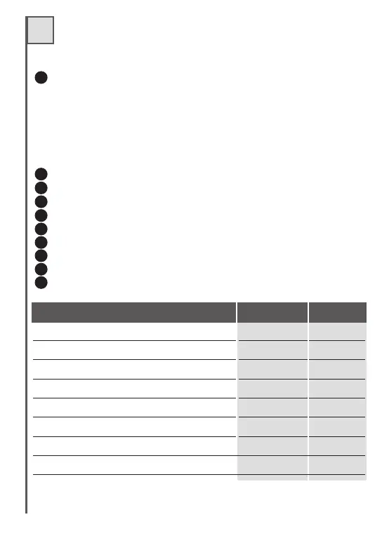
Description of parts
Connector for external connections
1-2 Power supply
3-4 Relay 1 output, no-voltage contact
5-6 Relay 2 output, no-voltage contact
7-8 Relay 3 output, no-voltage contact
9-10 Relay 4 output, no-voltage contact
11-12 Antenna
Jumper for power supply selection
Storage
Jumper for disabling of remote programming
Button P1 and LED L1
Button P2 and LED L2
Button P3 and LED L3
Button P4 and LED L4
Connectors for inserting relay modules.
Antenna connector (only on FM 400 SR2)
u.m.
Power supply FM 400 SR
Power supply FM 400 RB e R4
Consumption in standby at 24 Vdc
Relay contact max. capacity
Relay contact max. voltage
Operating temperature
Code storage with 24LC32
Code storage with 24LC64
Vdc/Vac 24
Vdc/Vac 12/24
mA 40
A0,5
Vac 24
°C -20+60
500
Codes
Codes 1012
RECEIVER TECHNICAL DATA
1
2
3
4
5
6
7
8
9
10
GB
32
Description of parts
Connector for external connections
1-2 Power supply
3-4 Relay 1 output, no-voltage contact
5-6 Relay 2 output, no-voltage contact
7-8 Relay 3 output, no-voltage contact
9-10 Relay 4 output, no-voltage contact
11-12 Antenna
Jumper for power supply selection
Storage
Jumper for disabling of remote programming
Button P1 and LED L1
Button P2 and LED L2
Button P3 and LED L3
Button P4 and LED L4
Connectors for inserting relay modules.
Antenna connector (only on FM 400 SR2)
u.m.
Power supply FM 400 SR
Power supply FM 400 RB e R4
Consumption in standby at 24 Vdc
Relay contact max. capacity
Relay contact max. voltage
Operating temperature
Code storage with 24LC32
Code storage with 24LC64
Vdc/Vac 24
Vdc/Vac 12/24
mA 40
A0,5
Vac 24
°C -20+60
500
Codes
Codes 1012
RECEIVER TECHNICAL DATA
1
2
3
4
5
6
7
8
9
10