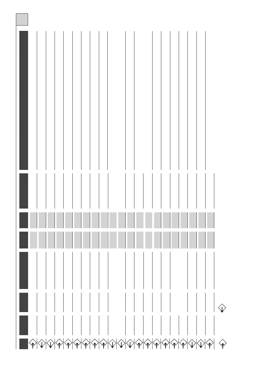
Connection to primary transformer
Connection to secondary transformer
During closing the gate reverses direction. Connect this input to the common if it is not used.
ATTENTION! Always connect the condenser to these terminals and not in parallel with the motor!
1
2
Linea
5A
Power supply
Connect to 230 V line.
3
4
Flasher
230Vac
1A
Movement indication
Switches on with motor in motion.
5
4
Lamp
230Vac
1A
Courtesy light
On form start of manoeuvre until 3 minutes after complete shutdown. Function included
on some versions.
6
12
N.O. Button
Open button
Starts gate opening.
7
12
N.O. Button
Close button
Starts gate closing.
8
12
N.O. Button
Impulse button
See table 2, functions 1 and 2.
9
12
N.C. Button
Stop button
Blocks all functions. Connect this input to the common if it is not used.
10
12
N.O. or N.C. Button
Multi-use Input
See table 2, functions 3 and 4.
15
14
Gate open indicator light
24Vac
2Wmax
Signal
Signals gate status with different flashes.
16
17
Auxiliary output
max24V
0,5A
Auxiliary output
Auxiliary output with free contact. Function included on some versions.
18
Rx Antenna
Braid
For the built-in receiver, use an antenna tuned at 433MHz. If a receiver is connected to the
provided connector, see the characteristics of the antenna as required by the manufacturer.
19
Rx Antenna
Control box
20
21
N.C. Contact
Limit switch open
Connect this inlet to the common if it is not used
27
28
Connector
29
30
Motor
230Vac
5A
Opening
Max 1100VA. Terminal 30 is common.
31
30
Motor
230Vac
5A
Closing
Max 1100VA. Terminal 30 is common.
32
33
Condenser
Breakaway
230Vac
TAB.1
GB
11
12
N.C. Contact
Photoelectric cell**
13
14
Auxiliaries
24Vac
300mA
24 V power supply
Power supply for photoelectric cell or other auxiliaries.
22
21
N.C. Contact
Limit switch closed
Connect this inlet to the common if it is not used
23-24
25-26
Connector
Input
Output
* ANTENNA: If a snap-in radio card is used, use care because on some models the connector for the connection of the antenna is
on the card itself.
** With the photoelectric cell obscured and the gate close, if a command is sent, the control box does not perform opening unti
l the photoelectric cell is freed. The command is memorized in
the K100 for 10 seconds, and indicated by the flasher coming on.
TERM. No.
TERM. No.
DEVICE
V
I max
FUNCTION
NOTES
30