1.
Connector for external connections
1-2 Power supply
3-4 Relay 1 output
5-6 Relay 2 output
7-8 Relay 3 output
9-10 Relay 4 output
11-12 Antenna
2.
Jumper for power supply selection
3.
Storage
4.
Jumper for rolling-code selection
5.
Button P1 and LED L1
6.
Button P2 and LED L2
7.
Button P3 and LED L3
8.
Button P4 and LED L4
9.
Connectors for inserting relay modules.
10.
Antenna connector TANGO SR
GB
28
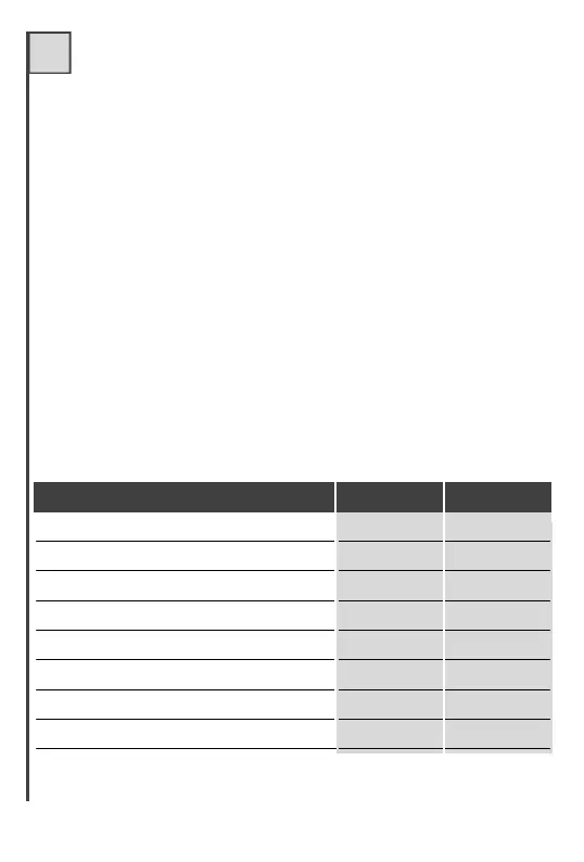
RECEIVER TECHNICAL DATA u.m.
Power supply Tango SR
Power supply Tango RB e R4
Consumption in standby at 24 Vdc
Relay contact max. capacity
Relay contact max. voltage
Operating temperature
Code storage with 24LC04
Code storage with 24LC16
Vdc/Vac 24
Vdc/Vac 12/24
mA 20
A 0,5
Vac 24
°C -20+60
170
(72 R.C.)
682
(292 R.C.)