TG-RX-MNL7, TG-RX-MNR7, TG-RX-MNP7 BASE BOARD
RECEIVER
WARNING! The receiver must NOT be opened by any other than a qualified installer. Make sure to
turn the electricity off before opening the receiver.
WARNING! Tele Radio remote controls are often built into wider applications. We recommend that
the system is provided with a wired emergency stop where necessary.
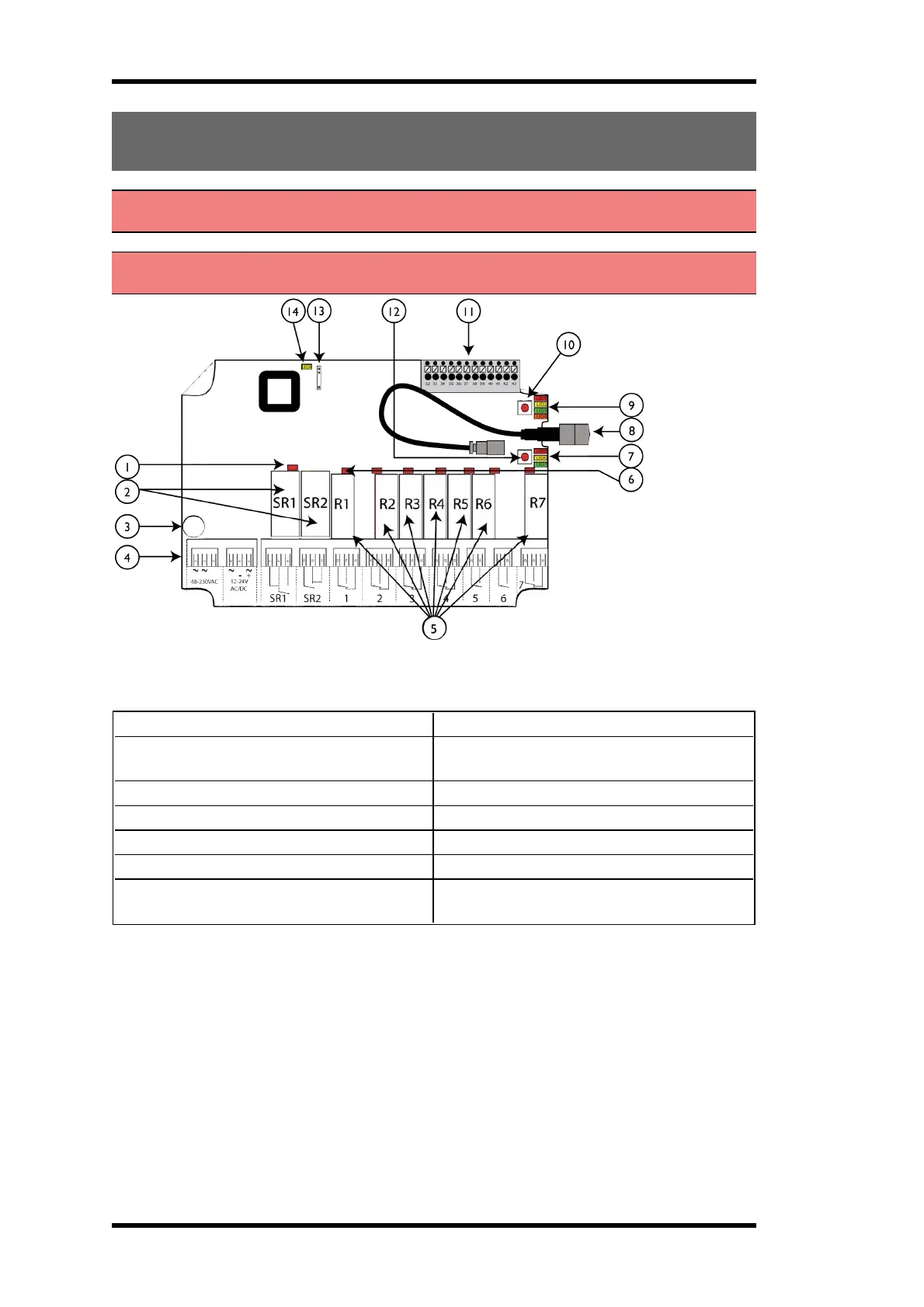
Base board:
1. LED representing stop relays 1+2 (red) 8. Antenna connector
2. Stop relays 1+2
9. Function LEDs 1-4 (1= red, 2= yellow, 3=
green, 4= orange)
3. Obligatory fuse 2A (slow) 10. Function button (Cancel)
4. Terminal block for input power 11. Terminal block for mixed I/O
5. Function relays 1-7 12. Select button (OK)
6. Relay LEDs 1-7 (red) 13. Programming connector
7. Function LEDs 5-7 (5= red, 6= yellow, 7=
green)
14. Power LED (yellow)
- 8 -
 Loading...