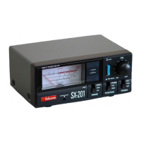
INSTALLATION
To install the SX-201/400 or SX-601/1000 simply connect coaxial cable direct to the antenna connector marked ANT
and the cable coming from the transmitter or from the linear amplifier to the connector marked TX.
POWER MEASUREMENTS
1. Select the RANGE (3) switch on the end-scale position value as to the power of the unit
2. Select the FUNCTION (4) switch in the power position
3. Select the POWER switch the FWD position to measure the direct power (from the radio to antenna) or REF
position to measure the reflected power (from antenna to the radio)
4. Select the power value can be read on the corresponding scale.
SWR MEASUREMENTS
1. Select the RANGE (3) switch on the end-scale position value as to the power of the unit.
2. Select the FUNCTION (4) switch in the CAL position .
3. Let the radio transmit and adjust the instrument by turning the CAL knob, position the end-scale index in the CAL
position.
4. Select the FUNCTION (4) switch in the SWR position
5. Read the SWR value in the above scale.
SPECIFICATIONS
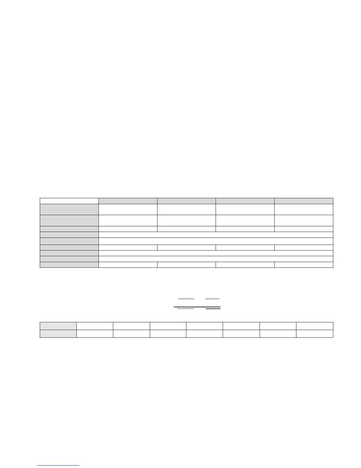 Loading...