EasyManua.ls Logo

Telecom SX-201 User Manual

Telecom SX-201
2 pages
To Next Page IconTo Next Page
Page #1 background imageLoading...
Page #1 background image
INSTRUCTIONS SWR/POWER METERS
SX-201, SX-400, SX-601, SX-1000
The SX-201/400 and SX-601 or SX-1000 POWER & SWR meter is the most efficient tool in wide range of semi-professional
measuring and control instruments. Measured values can be easily read in the large scale instruments.
The SX-201/400 and SX-601 or SX-1000 is an insertion type RF wattmeter and can be permanently fitted into a transmission
system for continuous monitoring of station working condition.
The unit can be work without external power supply but with 13.8DC power allows to light up the meter and shows
the active led corresponding to the selected RF coaxial line (for SX-601 and SX-1000)
SX-201 & SX-400
SX-601 & SX-1000
DESCRIPTION OF CONTROLS
1. POWER/SWR reading meter
2. Indicator adjustment
3. Power range switch
4. Function switch
5. FWD/Reflected Power/OFF switch
6. SWR calibration potential-meter
7. Average PEP to PEP switch
8. 200W/400W select switch
9. Antenna connector (PL) 1,8-160 MHz.
10. TX connector (PL). 1.8-160 MHz.
11. Power jack (13.8VDC) light up the meter and sensor 1/sensor 2 leds.
12. Antenna connector (N). 140-525 MHz. (SX-601) / 430-1300 MHz. (SX-1000)
13. TX connector (N). 140-525 MHz. (SX-601) / 430-1300 MHz. (SX-1000)
14. Led sensor 1.
15. Led sensor 2.
16. Sensor 1/Sensor 2 switch
Question and Answer IconNeed help?

Do you have a question about the Telecom SX-201 and is the answer not in the manual?

Telecom SX-201 Specifications

General IconGeneral
BrandTelecom
ModelSX-201
CategoryMeasuring Instruments
LanguageEnglish

Summary

SWR/Power Meter Instructions

General Introduction

Overview of SWR/Power meters, their use, and fitting into transmission systems.

Controls Description

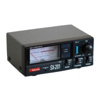
Detailed explanation of each control and its function on the SWR/Power meters.

Installation

Coaxial Cable Connection

Instructions for connecting coaxial cables to ANT and TX connectors for proper installation.

Power Measurements

Setting Up for Power Measurement

Steps to select range and function switches for accurate power measurement.

Measuring Forward and Reflected Power

Procedure to measure direct (FWD) and reflected (REF) power using the POWER switch.

SWR Measurements

Setting Up for SWR Measurement

Steps to select range and function switches for SWR measurement calibration.

Calibrating and Reading SWR Value

Procedure to calibrate the instrument and read the SWR value using the CAL knob and SWR scale.

Specifications

SWR vs. Reflected Power