EasyManua.ls Logo

Telecor SI-125 User Manual

Telecor SI-125
9 pages
To Next Page IconTo Next Page
Page #1 background imageLoading...
Page #1 background image
SI-125 Power Amplifier Manual 1
SI-125
Power Amplifier Manual
6205 Kestrel Road; Mississauga, Ontario; Canada; L5T 2A1 November 2016, Rev 0.5
Phone: (905) 564-0801 Fax: (905) 564-0806 www.telecor.com E:\T2-108\T2-M108-ABC\T2-M108-B.doc/AD
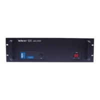
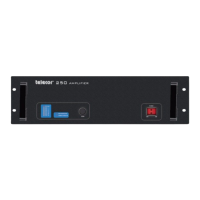
The Telecor SI-125 Power Amplifier delivers 125 watts of audio power intended to drive
industry standard speakers for sound reinforcement and paging systems. The amplifier will
accept either a balanced or single-ended input source. A sensitivity Input Level switch is
provided to select either the 1 V (0 dB) or 100 mV (-20 dB) input level. Output terminals are
provided for 4 , 8 , 25 V and 70 V speaker lines. The amplifier contains current limiting
circuitry on the output to protect it from overloading. The amplifier also has circuitry to protect it
from overheating.
The SI-125 Power Amplifier can have optional modules installed for additional functionality.
The PA-AM Power Amplifier Attenuator Module allows the amplifier to support a 25 V input
signal. The PA-MM Power Amplifier Monitor Module activates a relay under normal amplifier
operation. The PA-PM Power Amplifier Paging Module provides the amplifier with additional
inputs for a low impedance microphone and two balanced line level inputs.
The SI-125 Power Amplifier conforms to UL 60065 ETL listed mark with listing number
3059290.
The following symbols are on the amplifier and in this manual:
CAUTION
These servicing instructions are for use by qualified service personnel only. To reduce the risk
of electric shock, do not perform any servicing other than that contained in the operating
instructions unless you are qualified to do so.

Questions and Answers:

Telecor SI-125 Specifications

General IconGeneral
BrandTelecor
ModelSI-125
CategoryAmplifier
LanguageEnglish

Summary

Unit Description and Components

VU Meter

The 30 dB digital VU meter shows 0 dB when the amplifier is operating at its rated output.

High Temperature Indicator

Light illuminates when internal temperature exceeds limit, reducing output level.

Current Overload Indicator

Light illuminates when output current exceeds maximum, reducing output level.

Gain Control

Potentiometer adjusts amplifier gain, concealed behind a cover for protection.

Power Switch

Turns the amplifier on and off; the switch illuminates when the amplifier is turned on.

Fuse Protection

Protects the amplifier if the maximum current draw is exceeded.

AC Power Cord Connection

Connects the amplifier to a standard 120 V, 60 Hz grounded outlet.

Output Terminals

Terminals provided for 70 V and 25 V speaker lines, as well as 8 Ω and 4 Ω loads.

Accessory Module Slot

For optional accessories; a blank cover plate covers the slot if none installed.

Input Level Switch

Selects input level range (1 V or 100 mV) to match input signal.

Low Cut Switch Function

Reduces the low-end frequency response of the amplifier.

Input Terminals

Electronically balanced screw terminals for signal input; GND terminal for shield.

Clipping and Output Behavior

Installation and Connections

Input Connections Guide

Details screw terminals for balanced/single-ended inputs and shield grounding.

Output Connections

Explains connecting speaker loads to appropriate terminals based on impedance.

Operation

Optional Modules

Troubleshooting

Specifications

Limited Warranty Policy