SI-125 Power Amplifier Manual 6
Output Connections: The left terminal strip is the signal output of the amplifier. Terminals are
provided for 70 V and 25 V speaker lines, as well as 8 Ω and 4 Ω loads. Connect the speaker
load to the appropriate terminals depending on the load impedance. Class 2 wiring may be used.
The output of the amplifier is floating with respect to ground and should remain that way. Do not
connect the COM and GND terminals together. The GND terminal is provided for use with
shielded cable only.
To reduce the incidence of output audio being induced into other conductors, use twisted pair
wiring and keep the input and output wiring separated. To avoid overloading the amplifier,
ensure that the total speaker load impedance is no less than the values in the table below:
Output Terminals
Maximum Load /
Minimum Impedance
70 V 39 Ω
25 V 5 Ω
8 Ω 8 Ω
4 Ω 4 Ω
Line Impedance Measurements: Measure the amplifier’s load impedance using an audio signal
impedance meter (1 kHz) with the amplifier output disconnected. Also measure the impedance
of each side of the load to earth ground, which should be an open circuit. If it is not (i.e. there is a
fault to ground), isolate the fault and correct it. Do not operate the amplifier on a ground-faulted
output line.
Note: In school applications, there is often a privacy switch in the room. When this switch is
activated, it grounds one side of the room speaker line through a transformer. Make sure that all
these privacy switches are not in the Privacy position when measuring line impedance to ground.
These switches do not adversely affect the operation of the amplifier.
When measuring load impedance on a Telecor installation, disconnect the amplifier output from
the line, connect the impedance meter across the line, make sure the system is in an ALL CALL
mode, and then measure the line’s impedance and check for line ground faults.
Operation
• Before turning the amplifier on, ensure that:
o the speakers have an adequate power rating.
o the proper output terminals have been used.
o the gain of the amplifier is appropriate for the input signal supplied.
• If you are unsure about the Input Level and gain settings, turn the GAIN Control to
minimum before turning the amplifier on.
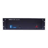
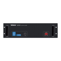
• Once the amplifier is mounted and wired, turn the unit on. The Power Switch will
illuminate. Watch the VU Meter on the front of the Power Amplifier. With no signal
connected, ensure that none of the LEDs are illuminated. If any LEDs illuminate, refer to
the Troubleshooting section
• With the signal applied, adjust the GAIN Control until an appropriate output level is
obtained. If the Current Overload or Clip lights illuminate, see the Troubleshooting
section
• To reduce the low frequency amplification, set the Low Cut switch to the CUT position.
 Loading...