Teledyne FLIR
Infrared Camera OEM
4
Equipment described herein is subject to US export regulations and may require a license prior to export. Diversion contrary to US law is prohibited.
Imagery for illustration purposes only. Specications are subject to change without notice. Rev. 100.
© 2021 Teledyne FLIR LLC. Approved for public release. Teledyne FLIR Approved [FLIRGTC-SBA-005]. All rights reserved.
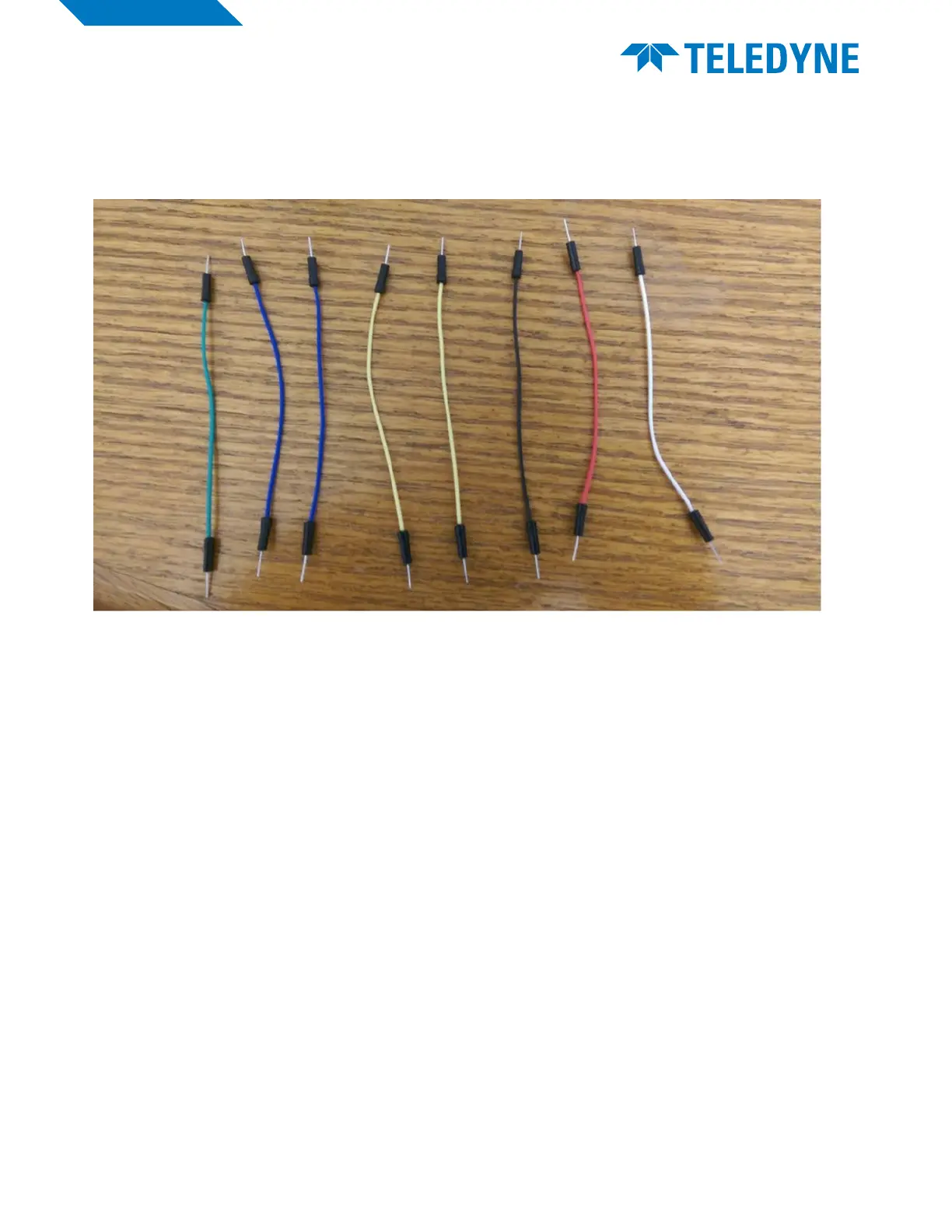
4 From the bundle of wires, select the following colors as shown. Colors can be interchanged as long
as you have the same number of wires for that color. (Example: photo shows 2 yellow wires, can be
changed with 2 of any other color)
5 Attach the wires from the breakout board to the following rows (as labeled) Follow the pictures
shown for gudiance. The key below shows where the pins go: (From breakout board to row #)
6 Key:
• a. White wire: Row (left) to Row (right)
• b. Yellow : Row (right) to Row (right)
• c. Yellow : Row (right) to Row (right)
• d. Blue Wire : Row (right) to Row (right)
• e. Black Wire: On row of holes next to red bar (right) to Row (right)
• f. Red Wire: On row of holes next to blue bar (right) to Row (right)
• g. Green Wire: Row (right) to Row (right)
• h. Blue Wire : Row (right) to Row (right)



 To Next Page