Do you have a question about the Teledyne TIENet 350 and is the answer not in the manual?
Lists contact details for Teledyne ISCO customer service and technical support.
Provides overarching safety advice and precautions for using the instrument.
Defines hazard levels (Caution, Warning, Danger) used in safety alerts within the manual.
Explains common hazard symbols used in the manual and on the equipment.
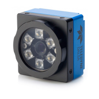
Explains the TIENet 350 sensor's function for measuring velocity and level.
Details sensor dimensions, cable length, temperature range, and measurement capabilities.
Describes how the 350 sensor can be integrated with LaserFlow systems for specific applications.
Lists available accessories like mounting rings, cables, and desiccators for sensor installation.
Provides guidance on inspecting and handling the system upon arrival, including damage reporting.
Outlines general safety warnings and hazard severity levels for installation procedures.
Explains how to use Expansion Boxes for extending cable length and connecting devices.
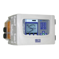
Details the process of preparing the Signature Flow Meter, including installing the external desiccator.
Guides users through electrically connecting the 350 sensor cable to the Signature flow meter.
Covers considerations for sensor placement, including uniform flow and avoiding poor channel conditions.
Describes options for mounting the sensor in pipes using Spring Rings and Scissors Rings.
Explains the system for installing sensors in sewers without entering manholes.
Details the grounding kit for protecting the sensor from lightning damage.
Guides on adding and configuring the 350 sensor within the Signature flow meter system.
Covers configuring velocity and level measurements, including advanced settings.
Explains how to adjust input velocity coefficients (A, B, C) for specific applications.
Details the process for setting or adjusting the level reading for the 350 sensor.
Provides recommended maintenance intervals and actions for ensuring proper sensor operation.
Explains how to update the TIENet device's firmware via the Signature Flow Meter.
Covers checking, renewing, and replacing the desiccant cartridge for the flow meter.
Guides on cleaning debris from the sensor while it is installed in the flow stream.
Instructions for cleaning the sensor's cable and outer surfaces with mild detergent.
Provides contact information for technical support regarding installation, operation, and maintenance.
Information on how to purchase replacement parts by contacting Teledyne ISCO Customer Service.
Introduces numbered error codes for troubleshooting erroneous flow data from the 350 Velocity data.
Explains how to download and import flow data from the Signature Flow Meter using .ddp files.
Guides on viewing and identifying velocity error codes within the Isco Flowlink software.
| Brand | Teledyne |
|---|---|
| Model | TIENet 350 |
| Category | Accessories |
| Language | English |