Note
24V lines that feed several loops will be split only on the panel output. It is
forbidden to connect in the field 24V lines to different loops.
TPS-74A or TPS-34A power supply will feed 24V to devices that belong to
one loop only. It is forbidden to bridge 24V between devices in the field that
belong to different loops.
3.1.4 Wiring planning – shielding
It is recommended not to conduct wiring outside of a building, because of the potential
risk of lightning strike. If necessary, shielded cables must be used. The shield must be
connected to the grounding by the grounding clamps on the panel.
3.1.5 Location
The device has to be installed indoors. Exposure to outdoor and weather conditions
must be prevented to avoid high humidity or dust and air contamination from external
sources.
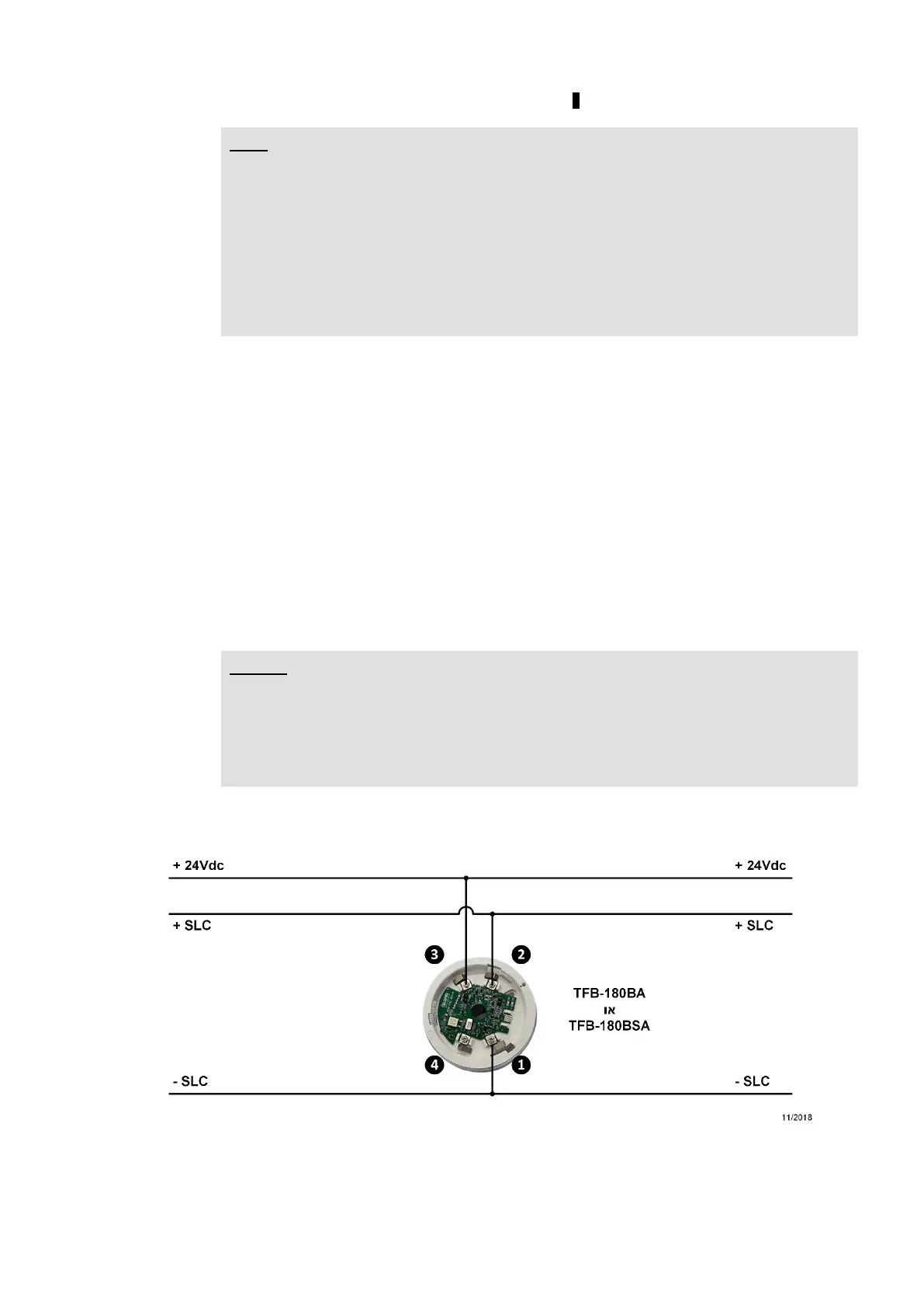
3.1.6 Connection of 24V power input and communication line to addressable
devices
Connect to the assembly the communication line for addressable devices (SLC) from
the panel, and 24VDC input from the panel or external power source, like TPS-74A or
TPS-34A .
Note
Check the wiring before making the connection, to ensure that is no short-
circuit in the wires.
The addition or removal of assemblies from the panel will be done when the
power sources to the panel (AC input voltage and batteries) are
disconnected.