EasyManua.ls Logo

Teleflex Marine XTREME NFB HELM - User Manual

Teleflex Marine XTREME NFB HELM
8 pages
Print Icon
To Next Page IconTo Next Page
Loading...
Xtreme
NFB
Helm
Part #SHX7606
Installer: these instructions contain important safety information
and must be forwarded to the boat owner.
NOTICE
Helms and cable assemblies are supplied lubricated ready for installation
,
do not add any lubricant to either assembly. Use of other lubricants
can cause damage to the steering cable, resulting in the cable seizing
or premature wear. Keep the cable and drive assembly clean during
installation. Dirt will damage the system and cause premature wear.
This notice does not include the engine output ram end of the cable.
NOTICE
These instructions describe how to install the Xtreme
NFB
HELM
and steering system. Helm part number SHX7606. XTREME
NFB
or No Feed Back helms have a clutch mechanism to prevent engine
torque at the steering wheel. This reduces operator fatigue by eliminating
the constantghting of the wheel. Instructions for installing steering
cables are also included.
In addition to this kit the following components are required for a
complete system:
Bezel Kit SBX76061 (90°)
SSCX64xx Cable (where xx is length in feet)
Engine Connection Kit (refer to Teleflex Marine catalog)
Steering Wheel (refer to Teleflex Marine catalog; Maximum
wheel diameter 16", Maximum wheel dish 5”)
Helms must not be disassembled for any reason. Failure to
reassemble correctly may lead to total failure of the system,
which could result in property damage, injury, or death.
WARNING
Before starting installation read these instructions and engine
makers instructions thoroughly. Failure to follow either of these
instructions or incorrect assembly can result in loss of control and
cause property damage, injury, or death.
DO NOT substitute parts from other manufacturers, they may cause
a safety hazard for which Teleflex Marine cannot accept responsibility.
To avoid excessive steering loads, and to get the best steering
performance, the outboard motor or outdrive trim tabs and tilt
position must be adjusted as instructed in the motor manufacturers
operation manual. Failure to do so can effect the performance of
the boat and its safe operation which may cause property damage,
injury, or death.
WARNING
WARNING
WARNING
DO NOT attach any electrical ground wires to the helm. This would
result in an electrolytic reaction to the steering system that may
result in system failure or greatly reduced service life.
WARNING
(Patents Pending)
web: www.teleflexmarine.com Teleflex Marine 640 North Lewis Road, Limerick, PA 19468 USA Telephone: 610-495-7011
Installation Instructions and
Owners Manual
Copy Part# IS-SHX7606, Rev. 3, 01/2012 Page 1 of 8
M A R I N E
Question and Answer IconNeed help?

Do you have a question about the Teleflex Marine XTREME NFB HELM and is the answer not in the manual?

Summary

Installation Preparation

Steering Cable Routing

Details routing the steering cable to balance engine torque and avoid bends.

Helm Installation Reference

Refers to separate bezel kit instructions for helm installation.

Steering Cable Installation

Steering Cable Connection Steps

Details steps for connecting the steering cable to the helm, including pin and sleeve handling.

Testing Cable Ram Movement

Describes testing cable movement by rotating the steering wheel to check ram extension/retraction.

Engine Connection

Lubrication and Securing Cable End

Instructions on lubricating the output ram end and securing the coupler nut.

Helm Parts Identification

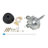
Lists components included in the helm kit with item numbers and descriptions.

Operation and Maintenance

Steering Torque and Trim Interaction

Explains how engine trim can affect steering torque and how to adjust.

Routine System Checks and Care

Details periodic checks for fasteners, cleanliness, corrosion, and cable condition.

Mounting Template

Template Photocopying Caution

Advises checking photocopied templates against measurements for accuracy.

Overview

The Teleflex Xtreme NFB Helm, part number SHX7606, is a steering system designed for marine applications. It features a No Feed Back (NFB) helm with a clutch mechanism that prevents engine torque from being felt at the steering wheel, thereby reducing operator fatigue by eliminating the constant need to fight the wheel. This system is designed for use with a maximum wheel diameter of 16 inches and a maximum wheel dish of 5 inches.

Function Description:

The Xtreme NFB Helm provides a smooth and responsive steering experience by isolating the steering wheel from engine torque. When the steering wheel is turned, the helm's internal gears engage with the steering cable, extending or retracting the cable's output ram to control the boat's direction. The NFB clutch mechanism allows the steering wheel to remain in position without constant input from the operator, even when the engine is under load or encountering prop torque. This feature enhances comfort and safety, especially during long periods of operation. The system requires additional components for a complete installation, including a bezel kit (SBX76061 for 90°), a steering cable (SSCX64xx where xx is length in feet), an engine connection kit, and a steering wheel.

Important Technical Specifications:

  • Helm Part Number: SHX7606
  • Bezel Kit: SBX76061 (90°)
  • Steering Cable: SSCX64xx (length in feet)
  • Maximum Wheel Diameter: 16 inches
  • Maximum Wheel Dish: 5 inches
  • Mounting Template:
    • One 3-1/4" (83 mm) diameter hole for the helm shaft.
    • Three 3/8" (10 mm) diameter holes for mounting bolts, arranged in a triangular pattern.
    • The mounting holes are positioned 2" (51 mm) from the center of the main hole, with one hole at the top and two at the bottom, 3-3/4" (95 mm) apart horizontally.
    • The distance from the top mounting hole to the bottom mounting holes is 2" (51 mm) vertically, and the bottom holes are 1" (25 mm) from the bottom edge of the template.
  • Cable Routing Radius: Minimum 8 inches to prevent hard steering and premature cable wear.
  • Bulkhead Hole Diameter: 1-1/2 inches for cable passage.
  • Compliance: ISO 8848, CE, ABYC, NMMA Member.

Usage Features:

  • Reduced Operator Fatigue: The NFB clutch mechanism eliminates engine torque feedback at the steering wheel, making steering easier and more comfortable, especially during extended use.
  • Smooth Steering: Designed for responsive and precise control of the boat.
  • Cable Installation Process:
    1. Position the steering wheel as shown in Figure 1 for correct orientation.
    2. Remove the pin from the cable entry spigot of the helm, keeping the tag on the pin.
    3. Remove the protective sleeve from the cable end, ensuring no dirt contaminates the lubricated end.
    4. Feed the cable into the upper helm spigot until it contacts the internal gears.
    5. Turn the steering wheel counter-clockwise to draw the cable fully into the helm. Continue turning until pressure is felt and a click is heard, indicating the locking mechanism has engaged. Continue turning until no further rotation is possible.
    6. Turn the steering wheel fully in the opposite direction to confirm the cable end fitting is retained.
    7. Replace the pin, ensuring it is fully seated and the tag remains attached for future maintenance.
    8. Turn the steering wheel fully to both extremes to confirm cable retention.
    9. Feed the spent travel tube (item 2, Figure 2) over the exposed cable end until it clicks into place in the helm spigot, then insert the pin (item 4, Figure 2) until fully seated.
    10. Rotate the steering wheel several times from stop to stop to observe the steering cable output ram movement. For starboard-mounted helms, clockwise rotation should extend the ram; for port-mounted helms, clockwise rotation should retract the ram.
  • Engine Connection: For engine-mounted systems, slide the output ram through the engine support tube and thread the cable coupler nut fully onto the support tube. For boat-mounted systems, attach the cable to the boat and engine according to the connection kit instructions.
  • Safety Tags: The "DO NOT REMOVE THIS TAG" on the pin is crucial for vessel safety during future steering maintenance.

Maintenance Features:

  • Regular Fastener Checks: After a few hours of initial operation and at frequent intervals thereafter, all fasteners and the complete steering system must be checked for security and integrity. Loose or lost fasteners can lead to steering system failure, loss of control, and potential injury or death.
  • Cleanliness: Keep all moving parts free from salt build-up and other foreign material to prevent steering problems. Periodically remove the cable, clean the support tube and telescopic end of the cable thoroughly.
  • Lubrication: Lubricate the support tube and telescopic end of the cable with a waterproof marine grease. The output ram end of the steering cable should also be lubricated with a good waterproof marine grease before insertion into the support tube. Important: Do not add any lubricant to the helm or cable assembly itself, as they are supplied pre-lubricated. Adding other lubricants can damage the steering cable, leading to seizing or premature wear.
  • Corrosion Inspection: Inspect periodically for corrosion. Any corroded parts must be replaced. Use self-locking hardware as originally supplied when replacing components.
  • Cable Inspection: Inspect the steering cable periodically for cracks or other damage. If any damage is found, the cable must be replaced immediately. A stiff cable is unsafe and requires immediate replacement.
  • No Disassembly: Helms must not be disassembled for any reason. Incorrect reassembly can lead to total system failure, property damage, injury, or death.
  • No Patching: Do not cover cracks with tape or other sealants, as this can lead to sudden, unannounced cable failure.
  • Trim Adjustment: Adjust outboard motor or outdrive trim tabs and tilt position according to the motor manufacturer's operation manual to avoid excessive steering loads and ensure optimal steering performance. Over-trimming can increase steering torque to the point where the wheel cannot be turned, even with the NFB system, potentially giving a false impression of a "locked" steering. This condition is more likely with jack plates and can only be resolved by reducing boat speed or engine trim. Adjust trim with extreme caution.

Teleflex Marine XTREME NFB HELM Specifications

General IconGeneral
BrandTeleflex Marine
ModelXTREME NFB HELM
CategoryBoating Equipment
LanguageEnglish

Related product manuals