Page 59 of 59
TVP Manual (full) March 2007 CE rev 03.doc
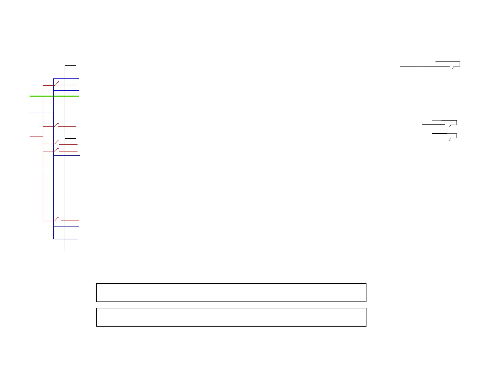
4.26 Isolated interface schematic
TVP side Pin Description Type Notes Customer side requirement
1
Operate unit CC Zero volt contact closure with any system ground will operate unit
2
System ground
3
Set point relay 1b. (duplicate of pin 28) SC Read back signal
4
Indicate common SC Customer supplied signal to be read back
5
Indicate power SC Read back signal
6
7
Frame Earth / Ground
8
9
Remote enable link to 24 to place in remote - factory supplied with connector
10
11
Operate cool coil 1 CC Zero volt contact closure with any system ground will operate unit
12
Indicate cool coil 1 SC
13
Operate defrost coil 1 CC Zero volt contact closure with any system ground will operate unit
14
15
Indicate defrost coil 1 SC Read back signal
16
Indicate defrost complete coil 1 SC Read back signal
17
Indicate common
18
19
20
21
Operate cool coil 2
22
Indicate coil coil 2
23
Opearte defrost coil 2
24
Pre - linked within factory supplied AMP plug to PIN 9
25
Indicate defrost coil 2
26
Indicate defrost complete coil 2
27
28
Set point relay 1a.
29
Indicate common
30
Set point relay 2
31
Indicate common
32
Analog out coil 1 (normally CO) SO Range 1 to 10 VDC = -172 to + 60 oC against system ground
33
System ground SO
34
35
24 VAC SO AC voltage protected by 2 Amp fuse
36
24 VAC SO AC voltage protected by 2 Amp fuse
37
Note
Voltage passed through an operate or system ground will disrupt the system.
All operate signals (contact closures) must be voltage free
Key
CC Customer supplied contact closure
SC System supplied contact closure
SO System output