Overview
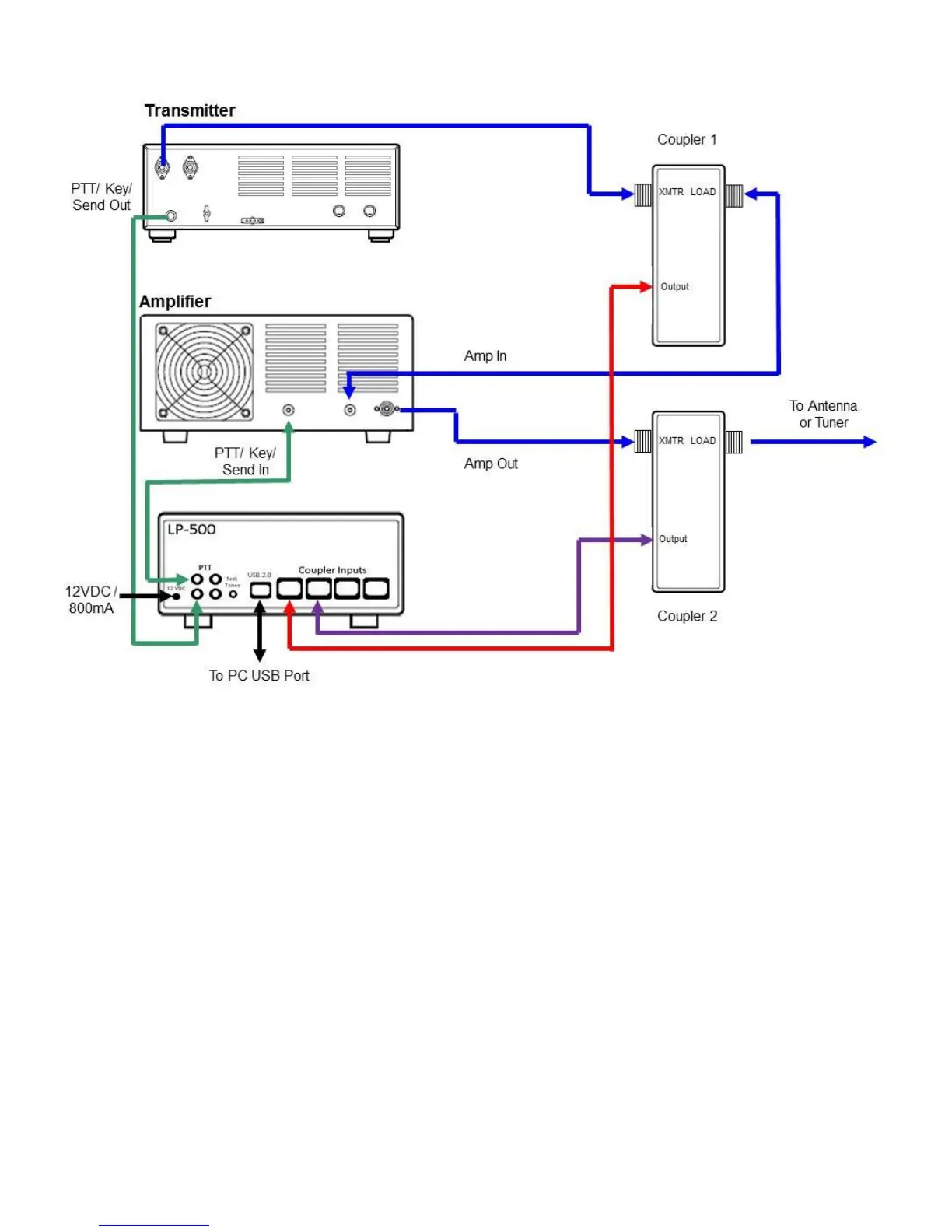
Fig.1. Shows installation with two couplers and PTT Alarm connections. The use of two couplers allows viewing of amplifier linearity with a trapezoidal
display. PTT Alarm connections are optional and designed mainly for older amplifiers with no built in protection.
The LP-500 Digital Station Monitor combines a state-of-the-art wattmeter and SWR meter with a task specific oscilloscope and spectrum analyzer, all
using a large, bright color TFT display. In the case of the LP-500, the display size is 5” diagonal. The LP-700 display size is 7” diagonal. Otherwise, the
two meters are the same. Any reference to the LP-500 in this manual also applies to the LP-700. The LP-500 also employs a low distortion audio signal
generator with a number of complex signals available, plus the ability to allow users to create their own test signals. The instrument can be used to
monitor the outputs of four different transmitters, or the inputs and outputs of two amplifiers as well as other combinations. The intent is for the user to be
able to monitor many aspects of his transmitted signal and ensure that his station is operating as cleanly as possible.
While it doesn’t completely replace dedicated oscilloscopes and spectrum analyzers, it performs almost all the tasks one would employ these
instruments to do, but does it much more conveniently, cost effectively and in many cases with better results.
While the LP-500 is a complex piece of test equipment, every effort has been made to make operation as simple as possible, with many automated or
linked functions. Operation of the LP-500 is mostly controlled through the six pushbuttons, but in the scope and spectrum modes there are a number of
touch screen controls, as well as a rotary digital encoder control. The six main buttons are associated with six “soft” buttons, which can also be
controlled via the touch screen.
The main modes of operation… Power/SWR meter, Waveform Scope and Spectrum Display… are controlled by the Mode button. The Mode button
remains in all modes, as does the Channel selection button. The 3
rd
button controls the range or gain of the meter in each mode. The other buttons are
soft keys whose function changes with mode.
A detailed list of modes and controls follows on the next pages, which will help the user get the most out of this meter.
 Loading...