Power/SWR Mode…
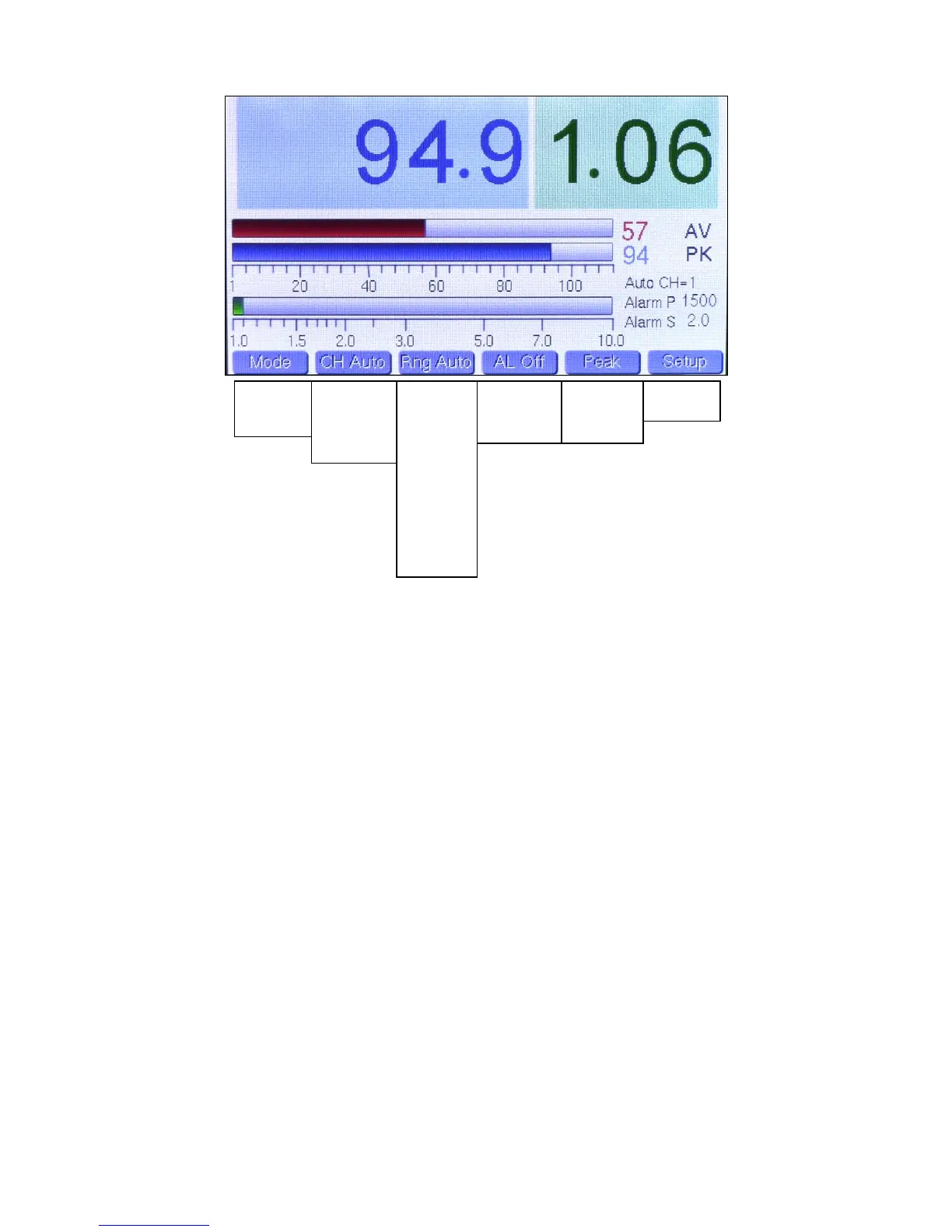
The above picture shows the Power/SWR mode, with menu choices listed below each button. The bottom choice in each list wraps around to the top.
Note: The pictures in this section were taken from v2.12 of the firmware and have changed slightly in later versions. The later versions have added a
peak hold power readout in the lower right.
Mode Button: Changes mode.
CH Button: Selects among the 4 coupler channels, and also offers an Auto Channel selection, which displays the channel with the highest power
reading. This mode is very useful for SO2R type contest operation. When in CH Auto, the current selected channel is displayed to the right of the SWR
bargraph, along with the current power and SWR alarm settings for that channel.
Range Button: Selects the desired bargraph range between 5W and 10KW in 11 steps, and also offers an Auto-Range choice.
The selection is indexed to the current channel selection and is saved in memory. As the range changes, the bargraph legends also change so that you
always graphically see the correct range and bargraph length. When changing to a higher range, there is some hysteresis built in so that the meter will
stay at the higher range unless power drops a certain percentage. This is done to prevent “hunting” on the edge of two ranges while operating, and
especially while tuning. Note: This choice can’t be changed when the CH button is in Auto.
Alarm Button: Selects the alarm status for each channel and is saved in memory. The alarm settings for the current selected channel are displayed to
the right of the SWR bargraph below the Auto CH display. This is true whether the channel is manually or automatically selected. These values are
entered on the Setup screen. If the alarm is tripped, the display indicates which channel tripped the alarm, and the chime sounds as well, with 1 chime
for CH1, 2 chimes for CH2, etc. The sequence repeats continuously until you stop transmitting, the fault is cleared or the alarm is set to OFF. The Alarm
P or Alarm S displays will change to red to indicate whether the trigger was due to a power fault or SWR fault. Note: This choice can’t be changed when
the CH button is in Auto.
Peak/Avg/Tune Button: Determines whether Average, Peak Hold or Tune power is fed to the large numeric power display. The hold time for Peak Hold
is adjustable in Setup. Tune is just peak hold with a very short hold time. Note: Smaller values of average and peak power are always displayed at the
end of the average and peak power bargraphs with 1W resolution.
Setup Button: This is a special button and displays a screen with all the adjustable user preference items. This will be covered as a separate mode later
in this guide. Tapping this button once changes to Setup mode, tapping again returns to Power/SWR mode. Tapping the Mode button will also return to
Power/SWR mode.
“Adjust” Knob: This controls an optical encoder which currently has two functions… to facilitate call sign entry in Setup by allowing the user to scroll
through alphanumeric characters, and to control the sweep rate in WFM mode when setting a User Preset. It does not function in factory presets. Slowly
turning this knob will result in smoother operation than rapid turning.
Power/SWR
Waveform
Spectrum
CH Auto
CH 1
CH 2
CH 3
CH 4
Rng Auto
Rng 5
Rng 10
Rng 25
Rng 50
Rng 100
Rng 250
Rng 500
Rng 1K
Rng 2.5K
Rng 5K
Rng 10K
(per channel)
AL Off
AL On
(per channel)
 Loading...