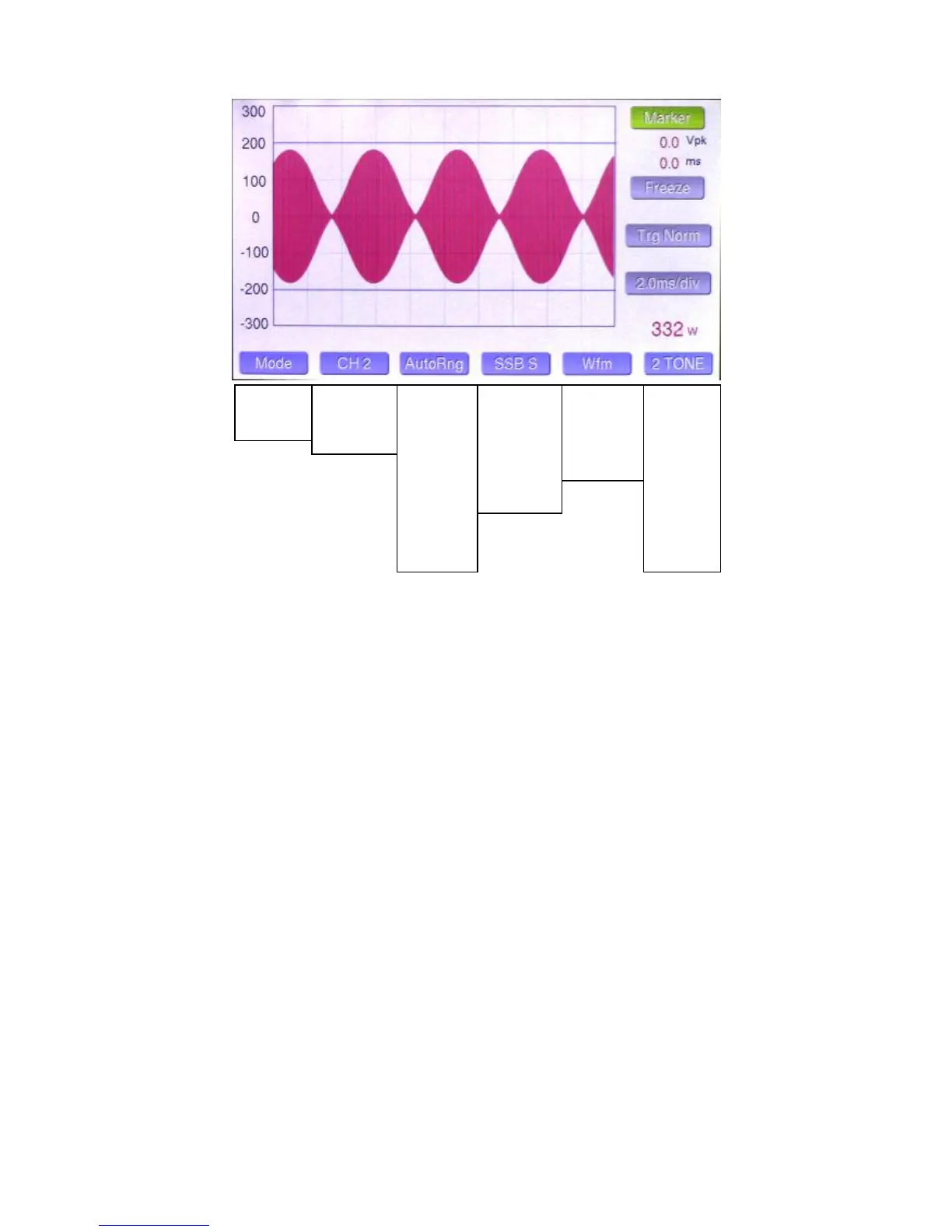
Waveform / ‘Scope Mode…
Mode Button: Changes mode.
CH Button: Selects among the 4 coupler channels. CH Auto is not offered in the ‘scope mode to avoid confusion. The channel selection for the ‘scope
mode is independent of the Power/SWR mode.
Range Button: Selects the desired power range between 5W and 10KW in 11 steps, and also offers an Auto-Range choice.
The selection is indexed to the current channel selection and is saved in memory. As the range changes, the vertical voltage legend changes as well to
indicate actual peak voltage at the output connector of the coupler. As with the Power/SWR mode, there is some hysteresis built into the auto-ranging.
Sweep Button: Selects the horizontal sweep rate / scaling. There are 5 presets… which select a combination of sweep rate and trigger mode optimized
for the indicated mode, as follows:
SSB Fast... 1.0 msec/division, Normal trigger
SSB Slow… 2.0 msec/division, Normal trigger
CW… 1.0 msec/division, +/- trigger (more on this below).
PSK Fast… 5.0 msec/division, Normal trigger
PSK Slow… 10.0 msec/division, Normal trigger
Note: The +/- trigger mode displays a split screen of the CW waveform with positive edge triggering on the left side of the screen and negative edge
triggering on the right edge. This provides more resolution for viewing the detail of the leading and trailing edges of the keying waveform.
In addition, there are three USER sweep settings which allow the user to select his own combinations of sweep rate and trigger style. More on this in the
Touch Screen Controls section.
Test Tone Button: This button selects the desired test signal to be fed to the transmitter. Choices are:
2 Tone+… Two tones plus “subcarrier” (Spectrum Mode)
Wnoise+… White noise plus subcarrier (Spectrum Mode)
Pnoise+… Pink noise plus subcarrier (Spectrum Mode)
2 Tone… Standard two tone test signal
Wnoise… White noise
Pnoise… Pink noise
400 Hz… 400 Hz sine wave
1 kHz… 1 kHz sine wave
User 1,2,3,4… These select custom tones that the user can record and save to memory in standard .wav format.
The test tone output of LP-500 is unbalanced line level audio with a source impedance of 250 ohms. This can be directly fed to the line input of most
radios. We are developing an interface box which will convert this audio to mic level balanced output, with a switch and attenuator to allow matching the
LP-500 output to a microphone and switch between them.
Power/SWR
Waveform
Spectrum
Rng Auto
Rng 5
Rng 10
Rng 25
Rng 50
Rng 100
Rng 250
Rng 500
Rng 1K
Rng 2.5K
Rng 5K
Rng 10K
SSB F
SSB S
CW
PSK F
PSK S
User 1
User 2
User 3
Wfm
½ Trap
Scope
Wfm/Trap
AM Mod
Wfm/Pwr
2 Tone+
Wnoise+
Pnoise+
2 Tone
WNoise
Pnoise
400 Hz
1 kHz
User 1
User 2
User 3
User 4
 Loading...