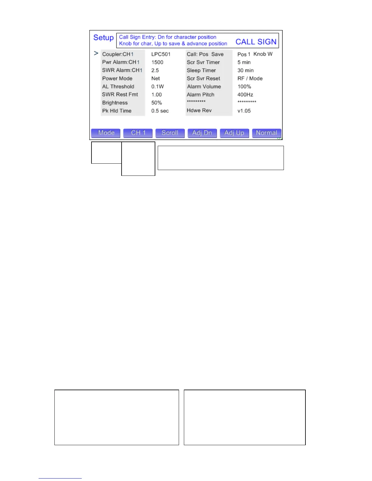
Setup Mode…
Mode Button: Changes mode
CH Button: Selects among the 4 coupler channels. There are three parameters that are channel specific… Coupler, Pwr Alarm and SWR Alarm. The
channel indicated next to each of these parameters is the one that is being adjusted.
Scroll Button: Allows the user to scroll down to the parameter he would like to change. This can be done by tapping repeatedly, or by holding the button
down for rapid scrolling through the parameters. When you get to the end of the list, the cursor moves back to the first parameter.
Adj Dn / Adj Up Buttons: Once the cursor is pointing to the parameter you want to adjust, using these buttons will allow you to adjust the setting up or
down. The exception is call sign entry. For this parameter, use the Dn button to select the horizontal position of the character you want to change, 1-9
from left to right. The use the knob to select the character (letter, numeral, punctuation) you want in that position. Pressing Up saves the character in the
call sign. NOTE: The character position counter automatically advances when you save a character, so you only need to use the Dn button if you want to
change one character.
Normal Button: Returns you to the Power/SWR screen
Here is a list of the various parameters and what they do, followed by a table of the default values.
Coupler… Selects the coupler model that is plugged into the selected channel…. LPC501, 502, 503, 504, 505
Power Alarm… Sets the power alarm trigger point for the selected channel… 10 to 2.5KW in 10W steps for LPC501, 20 to 5KW in 20W steps
for LPC502, 40 to 10KW in 40W steps for LPC503. This also sets the Peak Marker value.
SWR Alarm… Sets the SWR alarm trigger point for the selected channel… 1.50 to 5.00 in 0.50 steps
Power Mode… Selects power display type, either Net (F-R), ie. delivered power… or Fwd, ie. forward power.
AL/SWR Thresh… Minimum power required to activate the alarm system & SWR display. Use higher values to prevent false triggering from
other transmitters in multi-multi contest environments…1, 3, 10, 30, 100W. Higher values produce a more stable SWR display.
SWR Rest Fmt… Determines the graphic style for SWR display when not transmitting… 1.00, 0.00, Last (holds last value).
Brightness… Sets the screen brightness… 10% to 100% in 10% steps
Pk Hold Time… Sets the peak hold time in Peak power mode… 0.5, 1, 2, 3, 4, 5 seconds
Call: Pos Save… Allows the user to set a character position, and save the character to spell out his call sign. Adjust knob selects each character.
Scr Svr Timer… Sets the timeout values for the screen saver. Dims the screen to 10% after… 1, 2, 3, 4, 5, 10 minutes
Sleep Timer… Sets the timeout value for the screen to go to sleep… 10, 20, 30, 60 minutes and “Never Sleep”
Scr Svr Reset… Determines whether the meter will wake when you transmit, or if you wish to manually wake it with the Mode button.
Alarm Volume… Sets the volume of the alarm chimes… 10% to 100% in 10% steps. The chime sounds to help you set the right level.
Alarm Pitch… Sets the approx. pitch of the alarm chimes (the chimes are actually specified as musical notes)… ~300 to 900 Hz in 100 Hz steps
Peak Resp… Recently added screen. Allows the user to determine how the meter responds to very short peaks of power.
Hdwe Rev… Displays the current firmware revision.
The default settings for a standard LP-500 are shown below.
Coupler CH x… LPC501
Power Alarm CH1, CH3… 60W
(Power Alarm CH2, CH4… 1500W
SWR Alarm CH x… 2.0
Power Mode… Net (F-R)
AL Threshold… 3W
SWR Rest Fmt… 1.00
Brightness… 100%
Peak Hold Time… 1 sec
Call: Pos Char… Dn 1 Up L
Scr Svr Timer… 5 min
Sleep Timer… 30 min
Scr Svr Reset… RF / Mode
Alarm Volume… 100%
Alarm Pitch… 700 Hz
Peak Resp… 100 usec
Hdwe Rev… v2.xx
Power/SWR
Waveform
Spectrum
CH Auto
CH 1
CH 2
CH 3
CH 4
Note: New option for Peak Response time
added after Alarm Pitch option. See below
for details
 Loading...