EasyManua.ls Logo

TelePost LP-700 User Manual

Default Icon
14 pages
To Next Page IconTo Next Page
Page #1 background imageLoading...
Page #1 background image
1
LP-500 / LP-700
User Guide v3.1
Connections…
Power: 12-16 VDC @ 800 mA maximum, center pin positive, 2.5mm. The cable either has a white stripe on the positive wire, or ridges on the negative
wire, depending on the cable supplied. The meter also has a protection diode to prevent damage in case of reverse polarity. If unsure, use multimeter to
check the wiring before plugging it into the meter. The meter has a built in replaceable 1A fuse on the PCB for protection. We recommend a well
regulated supply with a 1A to 1.5A rating. An alternative is to use the accessory 12VDC jack on the rig if it can handle the current. You can also use a
12VDC power distribution strip like RigRunner connected to the main station DC supply. Sharing the meter power with other devices when the supply is
marginal could result in ripple caused by the high current switching of the LED backlight between on and off states.
PTT: For older amplifiers, loop the PTT (send, amp keying) between your amplifier and rig through the LP-500 using RCA connectors. Two isolated pairs
of connectors are provided for connecting two amplifiers. Use either pair for either amplifier.
Test Tones: Audio output for built in test tones. 3.5mm mono. Connects to the MIC or LINE input of the rig. An attenuator will be needed in the case of
mic input, as well as galvanic isolation (transformer). Interfaces designed for a sound card based RTTY setup should work well for this. We plan to offer
an interface box for this type of connection in the future, which will allow hot-switching between the mic and LP-500, isolation and level balancing
between them. This will ensure that testing can be done at normal speech levels.
USB 2.0: Connects to computer using standard USB cable (Type A to Type B connectors). Used for flashing firmware and interfacing to LP-500 VM and
Utility programs. Can be connected to USB 2.0 or 3.0 jacks on PC. No special drivers are necessary since the standard Windows drivers are used.
Couplers: Connect to corresponding jacks on the coupler(s) using supplied or user provided CAT5/6 shielded Ethernet cables. See Fig.1 below.
Question and Answer IconNeed help?

Do you have a question about the TelePost LP-700 and is the answer not in the manual?

TelePost LP-700 Specifications

General IconGeneral
BrandTelePost
ModelLP-700
CategoryMonitor
LanguageEnglish

Summary

Connections

Power Connection Details

Details for connecting the 12-16 VDC power supply, including polarity, fuse, and protection.

USB 2.0 Computer Connection

Connecting to a computer for firmware flashing and program interfacing via USB cable.

Overview of the LP-500/LP-700

Digital Station Monitor Functionality

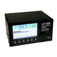
Combines wattmeter, SWR meter, oscilloscope, and spectrum analyzer on a color TFT display.

Power/SWR Mode

Power/SWR Mode Display and Controls

Explains the display and controls for Power/SWR mode, including bargraphs and readings.

Waveform / 'Scope Mode

Waveform / 'Scope Mode Display and Controls

Details the display and controls for waveform analysis, including sweep rate and triggers.

Waveform / 'Scope Mode, Continued

Touch Screen Controls for Waveform Mode

Describes cursor functions, freeze/unfreeze, trigger modes, sweep rate adjustment, and power display.

Spectrum Mode

Spectrum Mode Display and Controls

Explains controls for spectrum analysis, including gain, span, and averaging settings.

Setup Mode

Setup Mode Navigation and Controls

Describes accessing and navigating the setup menu for various parameters.

Recommended Usage Guidance

Power/SWR Mode Usage Tips

Guidance on setting range and alarm triggers for optimal Power/SWR monitoring.

Recommended Usage and Troubleshooting

Troubleshooting Common Issues

Addresses problems like meter not booting, screen flickering, and gain alarms.

LP-500 VM (Virtual Meter) Software

Virtual Meter Software Overview

Describes the virtual meter software, its functionality, and bidirectional control.

Using mikroBootloader to Flash Firmware

mikroBootloader Software Setup

Step-by-step guide on using the mikroBootloader software to upload new firmware.

Flashing New Firmware, Continued

Connecting Meter for Firmware Update

Instructions on connecting the LP-500 to the PC via USB and initiating the bootloader.

Uploading and Restarting with New Firmware

Process of uploading the HEX file and restarting the meter with new firmware.

Related product manuals