Recommended Usage of the LP-500, Continued…
Because the subcarrier must be stronger than the two test tones, this limits the peak power in the two tones, but still results in meaningful measurements
on a relative basis at full power, so that the user can see the degradation of the IMD products depending on amplifier settings, or when comparing one
amplifier to another. Note: The rig must be capable of passing 200 Hz for this mode to work. Most rigs will do this, or have SSB pass band options which
allow adjustment of the low frequency cutoff.
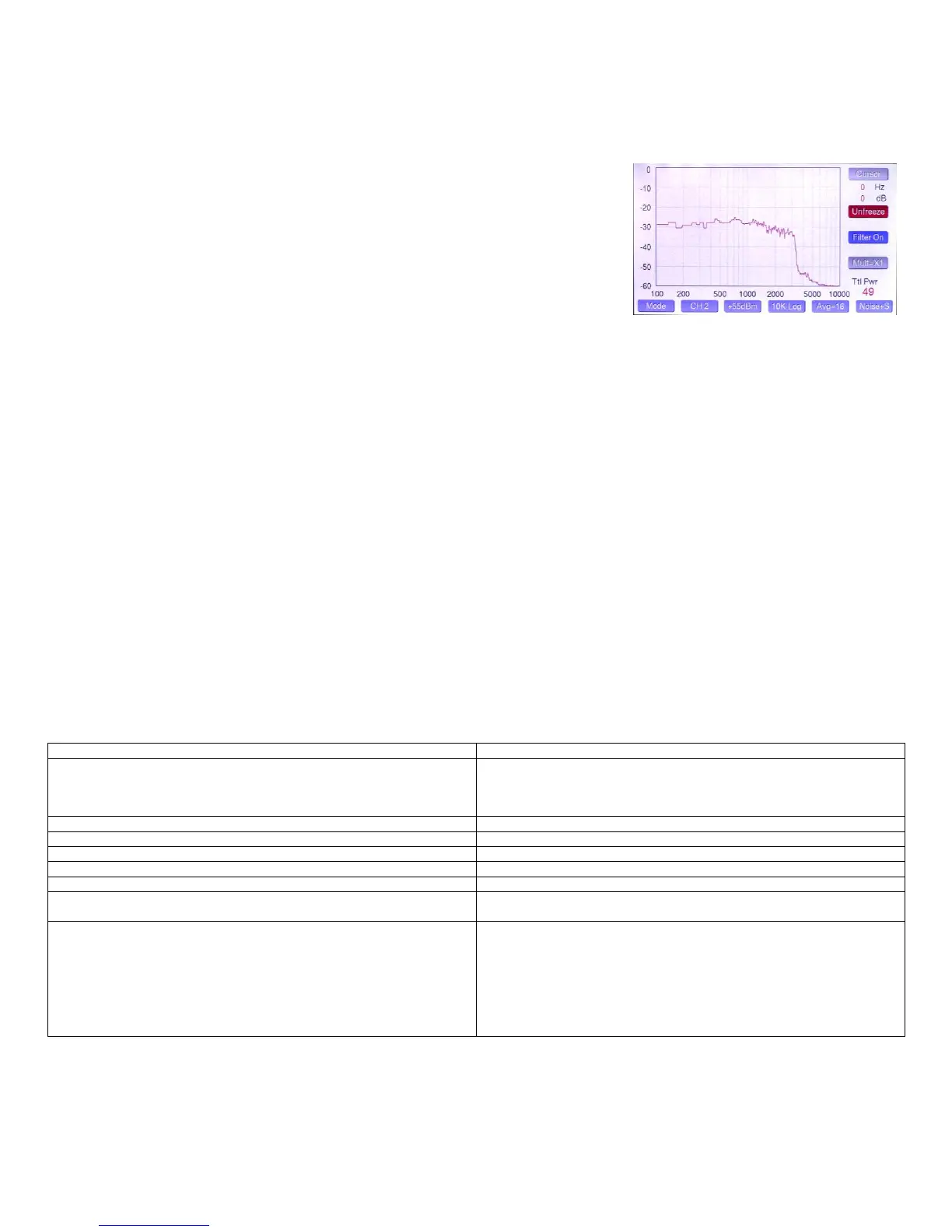
The Noise+ signal is especially useful in adjusting parametric equalizers in SSB modes. For AM
mode, a Noise signal is provided without the subcarrier. Keep in mind that the amplifier is being taxed
to the full power limit because of the power in the subcarrier signal, which is stronger than the
modulation signals. See picture at right…
In terms of settings, similar to what we saw in the other modes, the preamp gain settings are indexed
to the selected channel. Normally, the gain can be left at +65 dBm or +55 dBm depending on whether
you are using an amplifier, but occasionally when running very low power you may want to increase
gain to +45 dBm full scale. If you use too much gain, the gain button will turn red and you will see an
error message.
There are three span settings… 2.5, 5 and 10 kHz, with the option of either linear or logarithmic frequency scaling, with a 5X multiplier also available for
the 2.5 & 5 kHz Linear scales. Here are some recommended choices for some common tests…
Two Tone SSB… 2.5 kHz linear
Freq. Response… 5 or 10 kHz log
CW Bandwidth… 500 to 1000 Hz linear
SSB or AM Bandwidth… 5 kHz log
There is also a Span Multiplier button which decreases the span by a factor of 5:1 in the two narrowest ranges. Therefore, 2.5 kHz becomes 500 Hz and
5 kHz becomes 1 kHz. The span multiplier works in Linear modes and is useful for measuring the spectral width of CW or PSK signals. It should be
noted than when the multiplier is on, it slows the meter own considerably. We recommend setting the averaging to 2. It is self-cancelling in that the
Spectrum mode always starts with the multiplier off. This is done to eliminate starting in a slow mode.
When making IMD tests, it is advisable to use +55 dBm reference gain setting when doing tests at 100W, or +45 dBm reference gain setting when doing
tests at QRP levels. This not only lowers the noise floor, but places the signal and distortion products in a more linear range of the coupler detector. You
should try to set the reference setting so that the two tones are at an indicated level of -10 to -20 dBm relative to the reference at the top of the display.
The Filter button should be On whenever using a test signal with subcarrier to filter out the carrier artifacts and to restore the proper frequency scaling to
shift the display by the carrier frequency. This is automatic when selecting these test signals, but can be manually selected or deselected.
The averaging button can be set to taste. The higher the setting, the lower the noise floor, but also the slower the response. For frequency response
measurements with white noise, it should be set to 8 or 16 to make it easier to see the curve.
Troubleshooting…
Meter won’t boot past startup screen
Rotate Adjust knob. This is a bug caused by indecision (noise) in the
optical encoder on early meters (LP-500 serial number < 00030, LP-700
serial number <00018)). A free plugin mod is available to update the
encoder operation.
Meter screen flickers or tones are raspy
Insufficient power supply current capability
Ripple on patterns in ‘scope modes
Insufficient power supply regulation or chassis bonding
Low gain alarm in Trapezoid modes
Amplifier is off or not adjusted properly
Trapezoid vertical scale is low
Lower the Range setting, or select Auto
Trapezoid horizontal scale is low
Increase amplifier gain setting in LP-500
Channel alarm in Trapezoid modes
CH 2 or CH 4 must be selected for Trapezoid operation. Amplifier must be
connected to one of these channels.
Meter shows occasional high power peaks.
The solution depends on the source of the peaks and whether the user
wants to see them. Modest peaks can be caused by ALC overshoot in the
transmitter. Very large peaks could be caused by T/R relay arcs caused by
application of power before the relay has closed. Most rigs have an
adjustment to delay onset of power output after PTT is initiated.
In any case, the user can slow down the meter’s ultrafast response to
short spikes by choosing a longer Peak Resp time in SETUP.
 Loading...