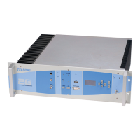
This document describes the TELERAD EM9000-2G VHF and EM9010-2G UHF Digital Transmitters, multi-mode, multi-frequency radio communication equipment designed for Ground to Air applications in civil and military aviation.
Function Description
The transmitters are designed to fulfill modern telecommunication requirements, supporting both voice and data transmission. They are multi-module systems intended for standard 19-inch rack installation (3U height).
Core Functionality:
- Modulation: Modulates voice signals received from a radio network (VCSS) or data from a communication system's upper layer. It supports traditional AM (A3E) modulation and, optionally, F3E (FM) modulation. Future developments are planned for G3E, ACARS, VDL2, VDL4 (VHF), and UDL2 (UHF) modes, utilizing emphasized FM, AM-MSK, D8PSK, and GFSK modulation types.
- Management: Manages various Human-Machine Interfaces (HMI) for configuration, operation, testing, and local/remote supervision.
- Self-monitoring: Incorporates built-in tests (Continuous Built-In Test - CBIT and Initiated Built-In Test - IBIT) and internal protection mechanisms against voltage surges, high temperatures, and SWR (Standing Wave Ratio).
Architecture:
The transmitters consist of eight main PCBs and modules:
- Power Supply Module: Located on the right side, it includes a Mains and Battery monitoring and switching PCB. "A" versions (EM9000A-2G, EM9010A-2G) also have an AC/DC converter providing +24VDC (VHF) or +28VDC (UHF) from Mains. "C" versions (EM9000C-2G, EM9010C-2G) are DC input only. This module monitors internal power supply sources and automatically switches to battery input upon Mains failure. It also manages a transmitter inhibition command if the battery voltage drops too low.
- Control PCB (CTRL11217): Located at the bottom, it acts as the central interconnection node for other components. It protects the amplifier module through slaving, SWR, or temperature information. It also houses electrical interfaces and connectors for DATA, JBUS, AF inputs/outputs, local/remote commands, and measurement conversion.
- Microprocessor-DSP Module (MIPR11005): The core of the transmitter, fitted perpendicularly to the control PCB. It contains a 32-bit MOTOROLA PowerQUICC I (MPC885) microcontroller and a 16-bit ANALOG DEVICE (AD2191) DSP. The microcontroller manages external communication ports (serial links, Ethernet), HMI, radio programming, internal protection, and built-in tests. The DSP handles all modulation and data/voice encoding.
- Synthesizer Module (SVHF25077 for VHF, SUHF25078 for UHF): Installed perpendicularly to the control PCB, it generates the non-modulated carrier supplied to the amplifier module.
- Amplifier Module (AMPV26260 for VHF, AMPU26246 for UHF): Constitutes the left side of the equipment. It includes power stages (exciter, pre-amplifier, amplifier), an I/Q modulator for carrier modulation, an I/Q demodulator for feedback information, a power filter for carrier harmonics, and a directional coupler to obtain "Direct power" and "Reflected power" information for calculating transmitted power, modulation rate, and SWR.
- Front Panel Management PCB (PAVE41160): Groups local commands and signals, providing visual indications for power supply status, radio status (Alarm, Carrier Presence, Modulation Presence, SWR > 2), and serial link activity. It also offers an "RF Test" BNC connector and interfaces for microphone input and headphone output.
- Display PCB: Manages the front panel screen/keyboard for local configuration.
Important Technical Specifications
General Characteristics:
- Frequency Range:
- EM9000-2G (VHF): 118-144 MHz (optional: 112-156 MHz)
- EM9010-2G (UHF): 225-400 MHz (optional: 225-406.1 MHz with F3E)
- Operating Modes:
- Basic: A3E (Voice) with various channel spacings (8.33 kHz, 12.5 kHz, 25 kHz).
- Optional: F3E (Voice FM transmission).
- Pending: G3E, ACARS, VDL2, VDL4 (VHF); UDL2 (UHF).
- Power Supply:
- Mains Input (A versions): 120/240VAC ±10% at 47-63 Hz.
- Battery Input (A and C versions): +24 VDC (21-31 VDC) for VHF, +28 VDC (21-31 VDC) for UHF.
- Consumption (typical values at 80% AM-modulated carrier):
- On Battery input: 14 A (+24VDC / +28VDC).
- On 115VAC Mains input: 3.9 A.
- On 230VAC Mains input: 2.2 A.
- Antenna SWR: Operation at nominal power until SWR of 2.
- Power Reduction: Gradual reduction if SWR > 2, module temperature > 70°C, or power supply voltage < 23.5VDC.
- Mechanical Characteristics: Weight < 14 kg.
- Climatic and Environmental Specifications:
- Operating temperature: between -20°C and +55°C.
- Relative humidity: 95% at 40°C (without condensation).
- Storage temperature: from -40°C to +80°C.
A3E Specifications (VHF EM9000-2G):
- Frequency Stability: < ±0.3 ppm (-20°C to +55°C).
- Output Power: Programmable from 2 to 50W (33 to 47dBm) by 0.5dB steps.
- Cyclical Ratio: 100% between -20°C and +35°C; 1min/5mins Tx/Rx cycle in extreme temperatures.
- Harmonic Distortion (m = 85%): ≤ 3%.
- Input AF Level: Adjustable from -30dBm to 0dBm (3dB steps).
- Adjacent Channel Power (ACP): < -70dBc.
- Spectral Purity: Harmonic lines < -36 dBm, Non-harmonic lines < -54 dBm.
F3E Specifications (VHF EM9000-2G, if installed):
- Output Power: Programmable from 7.5W to 75W (38.8dBm to 48.8dBm) by 0.5dB steps.
- Frequency Deviation: ±5.6kHz.
- Harmonic Distortion (ΔF = 5.6kHz): < 10%.
- Adjacent Channel Power (ACP): ≤ -60dBc.
- Spectral Purity: Harmonic lines < -36 dBm, Non-harmonic lines < -54 dBm.
Usage Features
Installation and Configuration:
- Mechanical Installation: Designed for 19-inch rack mounting. Requires sufficient air circulation and protection from radiant heat sources.
- Electrical Protection: Requires external circuit breakers for Mains (6AAC / 220VAC) and Battery (+VDC 16ADC / 127VDC) inputs.
- Software Configuration: Configurable via:
- Front panel screen/keyboard interface.
- RS232 terminal (Maintenance Connector).
- JBUS RS485 serial link.
- SNMP protocol over Ethernet.
- VoIP Configuration: Supports Voice over IP via ETH1 (J14 connector). Requires configuration of network parameters (IP address, subnet mask, gateway), operating mode (AUDIO VOIP), and SIP parameters (USERNAME, PORT).
- SNMP Configuration: Supports SNMP Protocol v1, v2c, and v3 for remote control and monitoring.
Operation:
- Local Operation: Accessible through the front panel screen/keyboard (for changing control to local, power output, preset channels, audio type, operating mode, frequency, and setup parameters) or via an RS232 terminal (offering a wider range of commands including network and SIP parameter adjustments).
- Remote Operation: Available via JBUS link (RS485) and SNMP link (Ethernet).
- PTT Protection: Programmable time-out from 0 to 300 seconds (5s steps).
Maintenance Features
Maintenance Concept:
- Safety Rules: Emphasizes strict adherence to safety guidelines, including electrical protection, proper ventilation, and qualified personnel for servicing internal components.
- Preventive Maintenance: Scheduled checks and cleaning operations (e.g., equipment cleaning annually).
- Corrective Maintenance: Procedures for fault localization, disassembly/reassembly of sub-assemblies, and adjustment operations.
Elements for Maintenance Help:
- Indicator Lights: PCBs and modules feature indicator lights to show the logic state of signals and provide validity information (e.g., S1 for "Hardware Reset" on MIPR11005, DS1 for PLL alarm on synthesizer modules, DS2 for PLL lock).
- Fault Localization: Faults can be quickly identified using the test menu on the front panel HMI (CBIT and IBIT reports specify faulty PCBs/modules).
- Disassembly/Reassembly Procedures: Detailed guide sheets (D1-D8) are provided for safe and correct removal and reinstallation of various modules and PCBs, including the amplifier, power supply, control PCB, microcontroller/DSP, and synthesizer modules.
- Operation Checks: Brief and in-depth checks for AM mode operation, including frequency, transmission, output power, AF compressor, audio bandwidth, SNR, and distortion level.
- Adjustment Operations: Procedures for local oscillator adjustment, phase and attenuation learning, and CTRL11217 PCB adjustment. These can be performed in the rack or on a table.
- Required Tools: Lists specific tools for maintenance, such as wattmeter, attenuator, LF generator/analyzer, modulation analyzer, frequency meter, spectrum analyzer, and test benches.
- Software Upload: A dedicated procedure (KITGB 40700003) is available for uploading software via a Web server interface.