Türkçe
Български
Детектор SensoMAG R20 е съвместим с всеки конвенционален пожарен панел с праг на
влизане в състояние ПОЖАР между 10mA и 15mA (между 10mA и 30mA с основа B24RD).
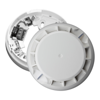
Детектор SensoMAG R20 е съвместим с 4 типа основи:
B B12L/U - Релейна основа (не се покрива от EN 54-5);
C B24 - Стандартна основа, нисък профил; B24-HP - Стандартна основа, висок профил;
ВНИМАНИЕ: Прочетете внимателно инструкцията преди да пристъпите към
инсталиране на детектора!
D B24D - Стандартна основа с Шотки диод;
ВНИМАНИЕ: Изключете захранването на линията преди да монтирате детектора!
6. Ако детекторът е заключен към основата, за да го отворите за почистване и поддръжка
трябва да използвате пластмасовия ключ. Леко натиснете с ключа в отвора на основата и
едновременно с това завъртете детектора обратно на часовниковата стрелка.
7. Тествайте детектора за правилна работа и светлинна индикация.
3. Монтирайте основата на тавана на помещението, като подберете винтове и дюбели според
монтажната повърхност.
4. Извършете електрически монтаж съгласно приложената схема.
5. Поставете детектора в основата и го завъртете по посока на часовниковата стрелка до
попадане в направляващите канали. Продължете да въртите докато маркерите на основата и
детектора съвпаднат - чува се щракване.
ВНИМАНИЕ: В случай, че сте свалили платката на детектора за поддръжка, за да я
монтирате обратно към корпуса, използвайте за ориентир цветния стикер в единия от
ъглите ѝ. Завъртете платката така, че отворът от лявата страна на цветния стикер да
съвпадне с репера от външната страна на корпуса. Отворът трябва да съвпадне с щифта
отдолу. Натиснете внимателно платката надолу, за да я фиксирате на място.
2. Ако желаете да “заключвате” детектора към основата отстранете зъбчето с триъгълна
форма (използвайте малка плоска отвертка) и отчупете пластмасовия ключ. Съхранявайте
пластмасовия ключ на достъпно място, за да можете при необходимост да свалите детектора от
основата.
E B24RD - Стандартна основа с Шотки диод и увеличен ток в алармено състояние.
1. Изберете подходящо място за монтаж на детектора. Следвайте дадените инструкции за
инсталиране. Забележка: Не инсталирайте детектора в близост до естествени източници
на топлина, например над готварски печки, фурни или камини.
Português
O detector SensoMAG R20 é compatível com qualquer central de incêndio convencional com
intervalo de alarme de fogo entre 10mA e 15mA (entre 10mA e 15mA com base B24RD).
B B12L/U - Base com saída de Relé (não cumpre a norma EN 54-5);
O detector SensoMAG R20 pode ser utilizado com 4 tipos diferentes de bases:
ATENÇÃO: Desligar a alimentação antes de instalar o detector!
2. Se desejar “fechar” o detector na base, remova o “dente” em forma de triângulo e quebre a chave
plástica da base. Guarde a chave plástica em local seguro para poder abrir o detector mais tarde.
4. Ligar a base do detector à central de incêndio utilizando o esquema de ligação.
ATENÇÃO: No caso de remover o PCB do detector para Manutenção, quando voltar a colocá-lo
procure a etiqueta colorida no PCB e orientá-la pela marca no corpo em plástico do detector
(visível do exterior). O espaço junto ao ponto colorido tem de coincidir com o pino no corpo em
plástico. Pressione cuidadosamente para fixar o PCB.
1. Escolha o melhor local para a Instalação do detector. Siga as instruções do manual de instalação
fornecido. Nota: Não instale o detector próximo de fontes de calor ex: por cima de fogões, fornos ou
locais com fogo.
C B24 - Base Standard, baixo perfil; B24-HP - Base Standard, alto perfil;
E B24RD - Base Standard com Diodo e aumento da corrente de alarme.
3. Instalar a base do detector no tecto utilizando elementos de fixação apropriados à superficie na
qual se pretende fixar o detector.
5. Introduzir o detector na base e rodar na direcção dos ponteiros do relógio. Continuar a rodar até o
detector estar fechado na base um click é audível.
D B24D - Base Standard com Diodo;
7. Testar o detector e indicação dos LED'S para um funcionamento correcto.
6. Para abrir o detector para Manutenção e limpeza tem de se utilizar uma chave plástica. Pressionar
ligeiramente a chave plastica na base e ao mesmo tempo rodar o detector no sentido oposto ao dos
ponteiros do relógio.
ATENÇÃO: Ler cuidadosamente este manual de instalação antes de instalar o dispositivo!
SensoMAG R20 dedektör yangın rejimi duşük eşik değeri 10mA ÷15mA arası olan her konvansiyonel
panel ile uygundur (değeri 10mA÷15mA B24RD tip soket ile).
B B12L/U - röleli soket (EN 54-5'e göre uyumlu değildir);
C B24 - standart soket, düşük profilli tasarım; B24-HP - standart soket, yüksek profilli tasarım;
SensoMAG R20 dedektör 4 ayrı soket ile kullanılabilir:
E B24RD - standart soket Schottky diod ile ve alarm durumunda artan akım.
DİKKAT: Servis (bakım, onarım) için dedektör kasasını sökmek gerekirse, yeniden takarken
PCB üzerindeki renkli etiketin plastic kasadaki işaretle denk gelmesine ve denk geldiğinde
hafifçe itilerek monte edilmesine dikkat ediniz.
DİKKAT: Montaj yapmadan önce, dikkatle montaj talimatını okuyunuz!
D B24D - standart soket Schottky diod ile;
1.Dedektörün montaj yerini seçiniz. Verilen montaj talimatlarına uyunuz. NOT: Dedektörü ısı
kaynağı yakınına monte etmeyiniz, örneğin ocak, fırın gibi.
3. Dedektör soketini korunan alanın tavanına, uygun vida kullanarak monte ediniz.
2. Dedektör ile soketi birbirine bağlamak istediğinizde, üçgen şeklindeki “dişi” (küçük yassı
tornavida yardımıyla) ayırın ve plastik anahtarı soketten koparın. Plastik anahtarı uygun bir yerde
muhafaza edin. İhtiyaç olduğunda bu anahtar ile dedektörü soketten ayırabilirsiniz.
4. Elektrik bağlantılarını ilgili şemaya göre yapınız.
DİKKAT: Elektrik montajı sırasında besleme olmamalıdır!
5. Dedektörü sokete yerleştiriniz ve saat yönünde, kılavuz kanallara yerleşene kadar çeviriniz.
Çevirmeye devam ediniz. Dedektör ve soket işaretleri karşı karşıya gelecektir ve kilitleme sesi
duyulacaktır.
6. Eğer dedektör soketinden üçgen şeklindeki “dişi” ayırdıysanız, dedektörün temizliği ve bakımı ile
ilgili plastik anahtarı kullanmalısınız. Hafifçe anahtarı soket deliğine bastırınız ve aynı zamanda
dedektörü saat yönüne ters çeviriniz.
7. Dedektörü çalışma ve ışıklı işaretler testine tutunuz.
ATTENTION: Read carefully this installation Instructions before installing the device!
The detector SensoMAG R20 can be used with 4 base types:
The detector SensoMAG R20 is compatible with any conventional Fire Panel with fire alarm threshold
between 10mA and 15mA (between 10mA and 30mA with B24RD fire base).
1. Choose the proper place for installation of the fire detector. Refer to the given installation
instructions. Note: Do not install the detector near to natural heat sources, e.g. above cookers, ovens
or fire places.
B B12L/U - Base with relay output (not covered by EN 54-5);
3. Mount the fire base on the ceiling of the protected premises using fixings according the mounting
surface.
4. Connect the detector base to the fire panel using the wiring diagram.
ATTENTION: Disconnect the line power before installing the detector!
E B24RD - Standard base with Schottky diode and increased alarm state current.
C B24 - Standard base, low profile; B24-HP - Standard base, high profile;
D B24D - Standard base with Schottky diode;
2. If you want to “lock” the detector to the base remove the little “tooth” (with the triangle shape)
and break the plastic key off the base. Keep the plastic key in safe place to be able to open the detector
later.
5. Insert the detector into the base and rotate clockwise until it drops into place. Continue to rotate
the detector until it locks to the base - a click is heard.
6. If the detector has been locked to the base, when opening it for a scheduled maintenance
service and cleaning you have to use the plastic key. Lightly press with the plastic key into the base
opening and at the same time rotate the detector head counter-clockwise.
ATTENTION: In case of removing the detector’s PCB for service maintenance, when mounting
it back, find the colored dot sticker on the PCB and align it to the mark on the plastic body
(visible from the outside). The hole next to the colored dot have to align with the pin on the
plastic body. Gently press downwards to fix the PCB in place.
7. Test the detector for proper operation and LED indication.
English
Conventional fire alarm Rate-of-Rise Heat Detector
SensoMAG R20 - Installation Instruction
SensoMAG R20 - Инструкция за инсталиране
Конвенционален пожароизвестителен максимално-диференциален
детектор
Detector termovelocimétrico incêndio convencional
SensoMAG R20 - Manual de Instalação SensoMAG R20 - Montaj Kılavuzu
Konvansiyonel sabit sıcaklık dedektörü
4
WIRING DIAGRAM / СХЕМА НА СВЪРЗВАНЕ / ESQUEMA DE LIGAÇÃO / ELEKTRIK TERTIBATI DIYAGRAM
Fire Panel / Пожароизвестителен панел
Central de Incêndio / Yangin kontrol paneli
+ (24V)
(Earth)
RL
RL
5
6
4. Power off the detector for 2 sec minimum. After resetting the detector
will enter in duty mode and the LEDs will light off.
TEST AND MAINTENANCE
1. Inspection for visible physical damage - weekly.
3. Apply the heat tester (Cordless Heat Detector Tester or Heat Tester
110V>240V) at a distance 20cm to test the heat part of the detector. Within
8 sec the fire detector will enter in fire condition. Both LEDs will light up.
1. Apply power to the detector.
3. Check and clean dust contamination - six months.
2. Wait for 30 sec.
2. Operational test in real conditions - monthly.
4. Check and clean base and head contacts and connections -
annually.
The service maintenance periods for the detector should be
executed as follows:
2. Проверка на работоспособността в реални условия-
ежемесечно
2. Изчакайте 30 сек.
3. Профилактично почистване на замърсяване от прах- 6 месеца
Сервизна поддръжка на детекторите трябва да се извършва:
4. Прекъснете за 2 сек. минимум захранването на детектора. След
подобен ресет детекторът ще се установи в дежурен режим и двата
светодиода ще изгаснат.
4. Профилактична проверка и почистване на контактната система -
1 година.
3. Въздействайте с топлинен тестер (Cordless Heat Detector Tester
или Heat Tester 110V>240V) върху детектора от разстояние 20см. В
границите на 8 секунди след въздействието детекторът трябва да се
установи в състояние “ПОЖАР”. Двата светодиода ще светнат
едновременно.
1. Външен оглед за видими механични повреди - ежеседмично
ТЕСТ И ПОДДРЪЖКА
1. Подайте захранващо напрежение на детектора.
A Manutenção do detector deve ser efectuada:
2. Teste operacional em condições reais - mensalmente.
3. Verificação e limpeza de sujidade semestralmente.
TESTE E MANUTENÇÃO
1. Alimentar o detector.
2. Esperar 30 seg.
3. Aplicar o teste de temperatura (Teste de Temperatura sem fios ou
Teste de Temperatura 110V>240V) a uma distância de 20cm para testar
o sensor térmico do detector. Em 8 seg. o detector entrará em estado de
alarme. Ambos os Led's acender-se-ão.
4. Retire a Alimentação ao detector no minimo durante 2 seg. Após
efectuar o reset, o detector entrará em modo de manutenção e os Led's
apagar-se-ão.
1. Inspecção de danos visíveis - semanalmente.
4. Verificação, limpeza da base, contactos e ligações- anualmente.
4. En az 2 s için beslemeyi kesiniz. Bu şekilde dedektör başlangıç
konumuna gelip, iki led sönecektir.
TEST VE BAKIM
Periyodik bakım sırasında aşağıdakileri yapınız:
3. 20 cm uzaktan test aparatı (Cordless Heat Detector Tester veya Heat
Tester 110V>240V) ile müdahale ediniz. 8 saniye içinde dedektör “yangın
”durumuna geçmelidir. İki led aynı anda yanmalıdır.
1. Dedektöre besleme veriniz.
2. 30 saniye bekleyiniz.
1. Fiziksel arızalara karşı gözle muayene - haftada bir.
2. Gerçek şartlarda çalışabilirlik kontrolü - ayda bir.
3. Kirlenme ve tozlanmaya karşı temizlik - 6 ayda bir.
4. Klemenslerin bakımı ve temizliği - yılda bir.
TEKNIK ÖZELLIKLER
TECHNICAL
SPECIFICATIONS /
ХАРАКТЕРИСТИКИ /
ТЕХНИЧЕСКИ
ESPECIFICAÇÕES
TÉCNICAS /
This manual is subject to change without notice! / Производителят си запазва правото за промени без предисвестие /
Este manual está sujeito a alteração sem aviso prévio! / İmalatçının, haber vermeden değişiklik yapma hakkı saklıdır!
100K*
*ATTENTION: When the EOL-module is only a capacitor, IT IS OBLIGATORY TO CONNECT a 100K resistor in parallel at the beginning of the line!
*ВНИМАНИЕ: Когато EOL-модула е само кондензатор, Е ЗАДЪЛЖИТЕЛНО да се добави паралелно в началото на линията съпротивление 100К !
*ATENÇÃO: Quando o módulo EOL (Fim de Linha) é somente um condensador, É OBRIGATÓRIO CONECTAR uma resistência de 100K em paralelo no inicio da linha.
*DİKKAT: EOL modül sadece kondansatör ise, zorunlu olarak 100 K'lık bir direnç hattın başlangıcına paralel bağlanmalıdır!
!
PCB from above
Платката, гледана отгоре
PCB
PCB
Mark on the outside of the plastic body
Репер от външната страна на корпуса
Marca na parte externa do corpo plástico
Plastik kasanın dışındaki işaret
LED Indication / LED Индикация /
LED Indicação / LED göstergesi
Blinking / Мига /
Piscar / Kırpmak
8 sec
OK
Light on / Свети /
LED sobre / LED açık
Light off / Не свети/
LED fora / LED kapalı
Colored dot sticker
Маркировка (точка)
Marka ponto
Nokta işareti
Intruder Alarm Panel /Алармен панел
Central de Intrusão / Alarm Paneli
B12L/U
+12V +12V
+12V
!
SensoMAG Bases / Типове основи /
Tipos de Bases / Soket
B12L/U
B12L/U, B24, B24D, B24RD
DoP No: 051
Tested by EVPU: N.B.1293
1293
22
Teletek Electronics JSC
14A Srebarna Str, 1407 Sofia, Bulgaria
EN 54-5:2017+A1:2018
Detector Class A1/R
SensoMAG R20
Conventional fire alarm
Rate-of-Rise Heat Detector
B24-HP
25.3mm
103mm
B24/B24-HP
18020572, RevF, 06/2022
1
!
B12L/U (SensoMAG R20 INTR)
Base / Основа / Base / Soket
Jumper
Latch/Unlatch
operation mode
Latch Mode
Jumper ON
Jumper OFF
Unlatch Mode
3
2
B24-HP
B12L/U, B24, B24D, B24RD
B24D B24RD
B24/
B24-HP
B24 / B24-HP / B24D / B24RD
Degree of protection. . . . . . . . . . . . . . . . . . . . . . . . Степен на защита . . . . . . . . . . . . . . . . . . . . . . . . . Grau de Protecção . . . . . . . . . . . . . . . . . . . . . . . . . Koruma Sınıfı . . . . . . . . . . . . . . . . . . . . . . . . . . . . . IP30
Class (in accordance with EN 54-5) . . . . . . . . . . . . Клас (в съотвествие с EN 54-5) . . . . . . . . . . . . . . Classe (de acordo com a norma EN 54-5). . . . . . . Sınıf (EN 54-5’e göre uyumlu) . . . . . . . . . . . . . . . . A1/R
Relative humidity resistance. . . . . . . . . . . . . . . . . . Bağıl neme dayanıklılık . . . . . . . . . . . . . . . . . . . . . (93 ± 3)% @ 40 CУстойчивост на относителна влажност . . . . . . . . Resistência à Humidade Relativa . . . . . . . . . . . . . °
- with base type B24, B24-HP and B24D . . . . . . . . - с основи B24, B24-HP и B24D . . . . . . . . . . . . . . - com base B24, B24-HP e B24D. . . . . . . . . . . . . . - B24, B24-HP ve B24D tip soket ile. . . . . . . . . . . . 20 mA / 12ё30V
Dimensions (incl. base) . . . . . . . . . . . . . . . . . . . . . Размери (с монтирана основа) . . . . . . . . . . . . . . Dimensões (incl. Base) . . . . . . . . . . . . . . . . . . . . . Ölçüler (soket dahil) . . . . . . . . . . . . . . . . . . . . . . . . ø102mm, h 42mm* / ø103mm, h 56mm**
Average current consumption in quiescent state . . Консумация в незадействано състояние . . . . . . Consumo em estado de repouso . . . . . . . . . . . . . . Ortalama Sükunet Akımı . . . . . . . . . . . . . . . . . . . . < 50µA
Operating Voltage Range . . . . . . . . . . . . . . . . . . . . Захранващо напрежение . . . . . . . . . . . . . . . . . . . Tensão de Funcionamento . . . . . . . . . . . . . . . . . . . Çalışma gerilimi . . . . . . . . . . . . . . . . . . . . . . . . . . . 9 - 30 V DC (Nom. 12/24VDC)
Weight (incl. base) . . . . . . . . . . . . . . . . . . . . . . . . . Тегло (с монтирана основа) . . . . . . . . . . . . . . . . . Peso (incl. Base) . . . . . . . . . . . . . . . . . . . . . . . . . . Ağırlık (soket dahil). . . . . . . . . . . . . . . . . . . . . . . . . 160g* / 170g**
- with base type B24RD . . . . . . . . . . . . . . . . . . . . . - с основа B24RD . . . . . . . . . . . . . . . . . . . . . . . . . - com base B24RD . . . . . . . . . . . . . . . . . . . . . . . . . - B24RD tip soket ile. . . . . . . . . . . . . . . . . . . . . . . . 33 mA / 12V; 49mA/24V; 57mA/30V
(Towards terminals +IN /+OUT) . . . . . . . . . . . . . . . (клеми +IN /+OUT). . . . . . . . . . . . . . . . . . . . . . . . . (Para Terminais +IN /+OUT). . . . . . . . . . . . . . . . . . (+IN/+OUT klemenslere göre)
- with base type B12L/U . . . . . . . . . . . . . . . . . . . . . - с основа B12L/U . . . . . . . . . . . . . . . . . . . . . . . . . - com base B12L/U. . . . . . . . . . . . . . . . . . . . . . . . . - B12L/U tip soket ile . . . . . . . . . . . . . . . . . . . . . . . 18 mA / 9V; 29mA/12V; 32mA/15V
Alarm state current: . . . . . . . . . . . . . . . . . . . . . . . . Консумация при аларма: . . . . . . . . . . . . . . . . . . . Corrente de Alarme: . . . . . . . . . . . . . . . . . . . . . . . . Alarm akımı:
2 2
Wire Gauge for terminals . . . . . . . . . . . . . . . . . . . . Сечение на използвания проводник . . . . . . . . . . Secção dos fios nos terminais . . . . . . . . . . . . . . . . Kullanılan kablo kesiti. . . . . . . . . . . . . . . . . . . . . . . 0.4mm ё 2.0mm
Output in alarm state at terminal RI . . . . . . . . . . . . Ток в алармено състояние на клема RI . . . . . . . Saída em estado de alarme no terminal RI . . . . . . Terminal RI alarm durumundaki çıkış akımı . . . . . . 20mA (max)/ -3.3V
Operational temperature range . . . . . . . . . . . . . . . Çalışma sıcaklık aralığı . . . . . . . . . . . . . . . . . . . . . -10 C ё +60 CРаботен температурен обхват . . . . . . . . . . . . . . . Temperatura de funcionamento . . . . . . . . . . . . . . . ° °
* B12L/U, B24, B24D, B24RD ** B24-HP