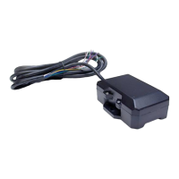
The Qtanium200 is a weatherproof Automatic Vehicle Location (AVL) unit designed for reliable long-term asset tracking applications. It is typically tethered to 12 or 24-volt systems but can operate independently for periods when disconnected. The device communicates with a server to store and monitor asset information.
Key Features and Technical Specifications:
- GPS Receiver: Internal 56-channel GPS receiver for accurate location data.
- Cellular Modem: Internal cellular modem (HSPA or CDMA) and antenna for data transfer between the asset and the server.
- Microprocessor: On-board microprocessor for data processing, storage, and external communications.
- Digital Inputs/Outputs: Supports 2 Digital Inputs and 2 Digital Outputs. These can be used to monitor various sensors such as PTO (Power Take-Off), seat belts, or other 12/24-volt positive or negative sensors.
- Digital Inputs: Can be connected to circuits with "ON" and "OFF" positions and configured for either positive or negative triggers. Circuit details must be noted for correct configuration via DIRECTOR.
- Digital Outputs: ConEx Digital Out 1&2 can be configured as an output via DIRECTOR. These outputs pull low with a maximum current of 250mA when activated. A relay is required for most applications. They feature over-current tripped protection; if tripped, the output must be changed to OFF or power cycled to reset the trip.
- Back-up Battery: Internal 5.2Ah 3.7V lithium-ion back-up battery, charged from a permanent external power supply (e.g., asset's battery). When fully charged, the internal battery can report for up to 6 months with a one-event-per-day schedule.
- Enclosure: IP66 sealed enclosure, making it waterproof, dustproof, and shock-resistant.
Installation Guidelines:
The Qtanium200 can be installed in trailers, vehicles, or other equipment.
Trailer Installation:
- Wiring: For standard trailer tracking, only power and ground connections are needed.
- Red Wire (+12/24V): Connect to the positive post of the asset's battery or another suitable permanent power supply. This connection must be fused (3 Amp).
- White Wire (Ignition): Connect to the same power connection as the Red wire. This connection must be fused (3 Amp) separately.
- Black Wire (Ground): Connect to the battery negative or asset chassis.
- Unused Wires: Blue (DI-1), Orange (DI-2), Green (DO-1), Brown (DO-2), Yellow (Reserved), Green/Black (TxD), Blue/Black (RxD), White/Blue (Reserved), Pink (Reserved) should be taped off to prevent accidental triggering.
- Pre-Installation (Wake-up Procedure): It is crucial to wake the device from hibernation.
- Use a drill battery or other temporary power source (9V-30V).
- Connect the Red (constant) wire to the positive terminal of the power source.
- Connect the Black (ground) wire to the negative terminal.
- Allow the Qtanium to power up (watch LEDs). Wait 1 minute.
- Connect the White (ignition) wire to the same positive power connection terminal for 30 seconds, then remove it. Failure to complete this step will prevent installation verification.
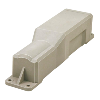
- Mounting Location:
- Designed to be mounted under the trailer, vertically on the side.
- Factors: length of power connection, no obstructions directly over the device (e.g., not directly above an axle to avoid blocking GPS reflective bounce).
- Mount with wiring facing down or with a "drip loop" to prevent water pooling.
- Use provided self-tapping screws or magnets. Ensure screws do not damage trailer parts.
- Route wiring carefully to the power location.
- Security: Qtanium200 and its wiring must be very secure for product longevity. Take extra time to verify mounting and wire routing.
- Alternate Locations: Face near the 7-way connector or on the side of a flat-bed trailer. On larger trailers, it can be mounted higher if requested by the customer or if a lower location doesn't work. Wiring must be carefully routed to prevent damage.
- Power Connections (Trailer):
- Made at the 7-way power connector between the trailer and truck, or at the trailer's power distribution block (if equipped, located in the rear between axles).
- 7-way Connector: Access rear wires. Connect Red and White wires together to the same power source.
- Connect to the Blue ABS power connection. If no ABS, connect to the tail/running light wire (Brown).
- Crucial: Do NOT connect to both ABS and tail/running light wires; this will damage the trailer and possibly the truck. Only ONE power source is needed.
- Ground connection to the White wire at the connector.
- Use provided shrinkable ring connectors or butt connectors.
- Rear Power Distribution Block: Access to run Qtanium200 wiring into the block. Use provided waterproof connectors. Loosen a connector, run Qtanium wires through with factory wires, and reattach.
- Power connection to the ABS power (blue wire). If no ABS, connect to tail/running lights (brown wire).
- Crucial: Do NOT connect to both ABS and tail/running light wires; only ONE power source is needed.
- Ground connection to the trailer's white wire.
- Use provided shrinkable ring terminals.
Vehicle/Equipment Installation:
- Wiring:
- Red Wire (+12/24V): Connect to the positive post of the asset's battery or another suitable permanent power supply. This connection must be fused (3 Amp).
- White Wire (Ignition): Connect to a positive input when ignition is ON or engine is running. This connection must be fused (3 Amp) separately.
- Black Wire (Ground): Connect to the battery negative or asset chassis.
- Unused Wires: Blue (DI-1), Orange (DI-2), Green (DO-1), Brown (DO-2), Yellow (Reserved), Green/Black (TxD), Blue/Black (RxD), White/Blue (Reserved), Pink (Reserved) should be taped off to prevent accidental triggering.
- Recommended Tools and Supplies:
- Tools: Panel Popper, Wire stripper-multi gauge, Crimp Tool, Wire cutters, Cordless drill (variable speed reversible), Assorted screwdriver bits, Magnetic nut-drivers, Skew-driver (right-angle screwdriver adaptor).
- Supplies: Ring Terminals, Zip-ties, Electrical Tape, Spare fuses (various sizes/values), Self-tapping screws.
- Power Connections (Vehicle):
- Connection Method: All connections must be soldered (preferred) or poke and wrapped. Scotch-Loc or T-Tap connections are NOT approved and will be billed for correction if found during QC inspection.
- Fuse Holders: Use supplied fuse holders; place them as close to the connection point as possible to protect the vehicle.
- Identifying Wires:
- Remove interior trim to access wiring.
- Attach fuse holders to Constant and Ignition wires.
- Recommended to locate constant and ignition wires at the ignition switch, but be aware of potential difficulties or low amperage control wires. Installers' experience should guide alternative appropriate locations.
- Always use a multimeter to identify wires.
- Constant Power Connection:
- Wire has power regardless of key position.
- Connect the Red wire from Qtanium200 here.
- Connect to (+) battery post or (+) post on the alternator.
- Insert inline weatherproof fuse-holder with a 3A fuse.
- Connect the Black wire to the vehicle's chassis.
- If the vehicle has a main battery disconnect, connect the Red wire on the battery side (hot at all times) unless otherwise advised.
- Ignition Power Connection (Engine Run Signal):
- Wire has power when the key is in ON/RUN position and while the engine is cranking; no power when key is off/removed.
- Connect the White wire from Qtanium200 here.
- Recommended: R-terminal at the alternator or the hour meter. If not available, engine oil pressure switch or fuel pump circuit can be used.
- Identify R-terminal: 12V or 24V present ONLY when the engine is running. Use a multimeter.
- Connect the Qtanium's Pink wire here. Insert a 3-Amp inline fuse in a weatherproof fuse holder.
- Note: Not recommended to connect to vehicle's ignition wires, as this can lead to inaccurate engine hour calculation if ignition is left on without the engine running.
- Poke & Wrap Method (for internal connections):
- Strip: Remove ¼" insulation from source wire, 1" from fused Qtanium200 wire.
- Divide: Use a tool to divide source wires down the middle.
- Poke: Insert stripped portion of fused wire through the middle.
- Twist: Twist fused wire around source wire (4-6 times).
- Lock: Bend fused wire back onto wrapped section.
- Secure: Apply high-quality electrical tape and a zip-tie over the connection.
- Ground Connection:
- Locate a strong metal spot near the transceiver.
- Scrape away paint/coating.
- Use a star washer between metal and ground terminal.
- For aluminum/fiberglass bodies, run lead to battery and connect to negative side.
- Do NOT use existing factory ground wires to avoid interference.
- Mounting Location (Vehicle/Equipment):
- Conceal all equipment and wiring.
- Mount to a flat surface; avoid curves, dips, or humps.
- Mount to vehicle chassis using mounting tabs, screws, or zip-ties.
- Check behind drilling locations to avoid fuel/brake lines, wiring harnesses, etc.
- Avoid touching existing factory harnesses to prevent electrical shorts from vibration.
- Mount with internal antenna having a clear view of the sky.
- Ensure no physical interference with movable equipment (seats, pedals, hinges, A/C vents).
- Crucial: NEVER mount any component to vehicle air lines; damage can cause catastrophic failure.
- Unapproved Mounting Locations:
- Truck bed.
- Near RFI sources (vehicle computer, alarm, AM/FM radio, CB radio, or their antenna paths).
- Any location blocking the internal antenna's clear view of the sky.
- The Qtanium200 is waterproof, dustproof, and shock-resistant, so it can be mounted externally if the antenna has a clear view of the sky.
Administration:
- Document as much information as possible for all installations.
- Record the full 17-digit VIN.
- Document the Make, Model, Year, and Asset number of the vehicle/equipment.
Verification:
- Live Test: Vehicle must be outside with a clear view of the sky.
- RIMU Auto Verification: Access via smartphone/smart device at
https://onlineavl2sup-us.navmanwireless.com/AVL3WebSysadmin.
- If no username/password, contact Navman Wireless Support at
us.dispatch@navmanwireless.com or 877-778-2478.
- Follow on-screen prompts to complete verification.
- ConEx/VD Verification: Contact Navman Wireless Support at
us.dispatch@navmanwireless.com or 877-778-2478.
LED Light Confirmation:
LEDs on the Qtanium200's face indicate functionality. While final verification requires calling support, these LEDs help confirm correct connections.
- COMM LED (Orange) – Communications LED:
- Off: Modem off.
- Slow Blinking: Comm on – searching.
- Fast Blinking: Network available.
- Alternates from Solid to Fast Blink: Registered but no inbound acknowledgment.
- Solid On: Registered and received inbound acknowledgment.
- GPS LED (Green) – GPS LED:
- Off: GPS receiver off.
- Slow Blinking: GPS receiver on.
- Fast Blinking: GPS time sync.
- Solid On: GPS fix acquired.
Technical Support:
- Hours: Monday – Friday, 7am – 7pm (Central Time).
- Email:
us.support@navmanwireless.com.
- Toll Free Phone: 877-778-2478.
- Local Phone: 847-832-6950.