Care and Feeding of Telex Radio Dispatch Systems
C-6200 Setup
Phase 4 Design, Inc.
Dave Grant / dgrant@hostnw.net
425.402.7308
11/5/2010 Page 11 of 18
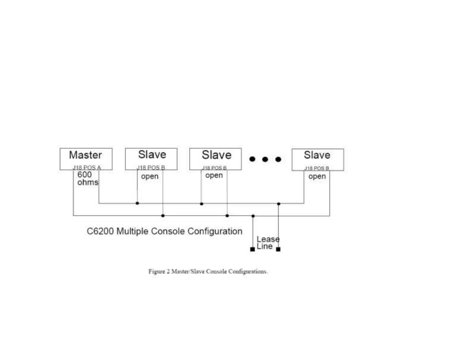
Figure 2 shows a basic configuration, the C-6200 could also be the master in this configuration.
NOTE: If any of the consoles connected in parallel are not C-6200’s, then all the C6200’s should be
configured as slaves. Additionally, J18 (Line 1) or J17 (Line 2) should be used as a TX line
impedance correction if there are consoles other than the C-6200 connected in parallel. J18 (Line 1)
or J17 (Line 2) position “B” adds another 600ohms to the output TX line. J18 (Line 1) or J17 (Line
2) Position “A” is straight through.
Aux Connector: