Connect the Antenna and Place the Unit
Connect the antenna to the antenna port, and press the RSSI button
on the side of the unit to put the LEDs into RSSI display mode. When
you have found a location that provides 2 ½ bars or more (LEDs 4 and
5 solid, and LED 3 flashing or solid), install the mounting screws and
attach the TG-1 Express to the mounting screws. Press the RSSI button
again to return the LEDs to normal display mode.
Activate the TG-1 Express
The last step is to trigger an alarm from the panel to activate the TG-1
Express. Note that the first alarm will activate the TG-1 Express with
the Telular Communication Center, and will not be sent to the central
station.
Optional Steps
Configure and Connect the Supervisory Trip Output
If required, configure the relay output using a butt set or phone set,
referencing the programming instructions on the back of this guide.
By default, the relay will trip for any system trouble condition detected
on the TG-1 Express. Connect the relay output (pins 1 and 2 on the
terminal block) to a 24 hour zone on the alarm panel.
Configure and Connect the Trip Input
The trip input may be configured to provide supervision independent
of the alarm panel, for applications such as external sensors and
tamper protection. Configure the trip and restoral reporting (they are
disabled by default) and the swinger setting using a butt set, and
connect the trip input and ground terminals to the external sensor.
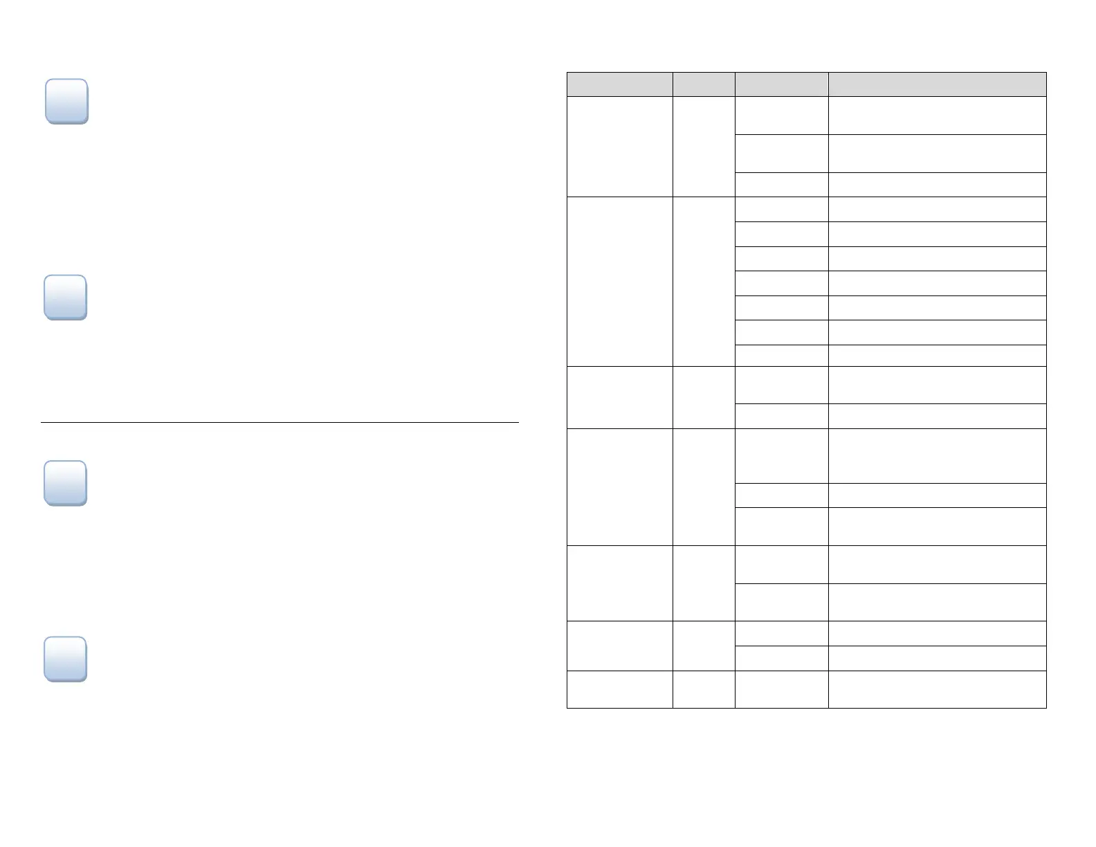
LED Indicators (normal mode)
LED Symbol Color Showing Indication
LED #1
Activation
Green
Solid On
Unit is activated at the message
center and enabled
Off
Unit not activated at the message
center
Flashing Unit is activated but disabled
LED #2
STC
(System Trouble
Condition)
Red
Off ALL OK
1 Flash STC – Low Power Failure
2, 3 Flashes N/A
4 Flashes STC – No Service Condition
5 Flashes STC – Radio Failure Condition
6 Flashes STC – Dial Tone Failure
7 Flashes STC – Panel Presence Failure
LED #3
MODE
Yellow
Flashing
Telguard TG-1 Express
communicating with alarm panel
Off Idle state
LED #4
Acknow-
ledgement
Red
Flashing
When flashing with LED #1 unit
has failed activation. CALL
TELGUARD TECHNICAL SUPPORT
Off TG-1 Express initialized
On
TG-1 Express is waiting for response
from Telular Communication Center
LED #5
Radio
Green
Short Flash (1
sec)
Radio receiving message
Long Flash (2
sec)
Radio sending message
LED #7
Trip Input
Green
Solid On Trip input activated
Off Trip input not active or restored
LED #8
Power
Red Solid On Power connected to unit
 Loading...