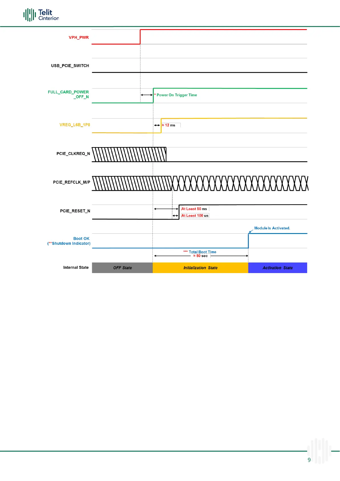
Figure 4: FN990 Family Power ON Sequence – PCIe EP mode (USB_PCIE_SWITCH: Low)
Note: To verify if the FN990 Family has powered up properly, please follow the
indications below:
* Power on trigger time is the interval between VPH_PWR to
FULL_CARD_POWER_OFF_N: this could be null (0 ms) if the customer application
requires turning on the module automatically.
** Monitoring BOOT_OK (Shutdown indicator) pin. When the status translates to
high, the module boot-up process is complete. To use BOOT_OK (Shutdown
indicator), the shutdown indication function must be enabled through the
AT#SHDNIND command. (please refer to the AT Reference Guide document)
*** The stated total boot time is an approximate measure of the latest SW and HW
configuration. The boot time may be lengthened or shortened depending on the
module configuration, firmware, or hardware version.
Note: Active low signals are labeled with a name ending with “_N”.

 Loading...