FN990 Family Hardware Design Guide
7.3 Communication Ports
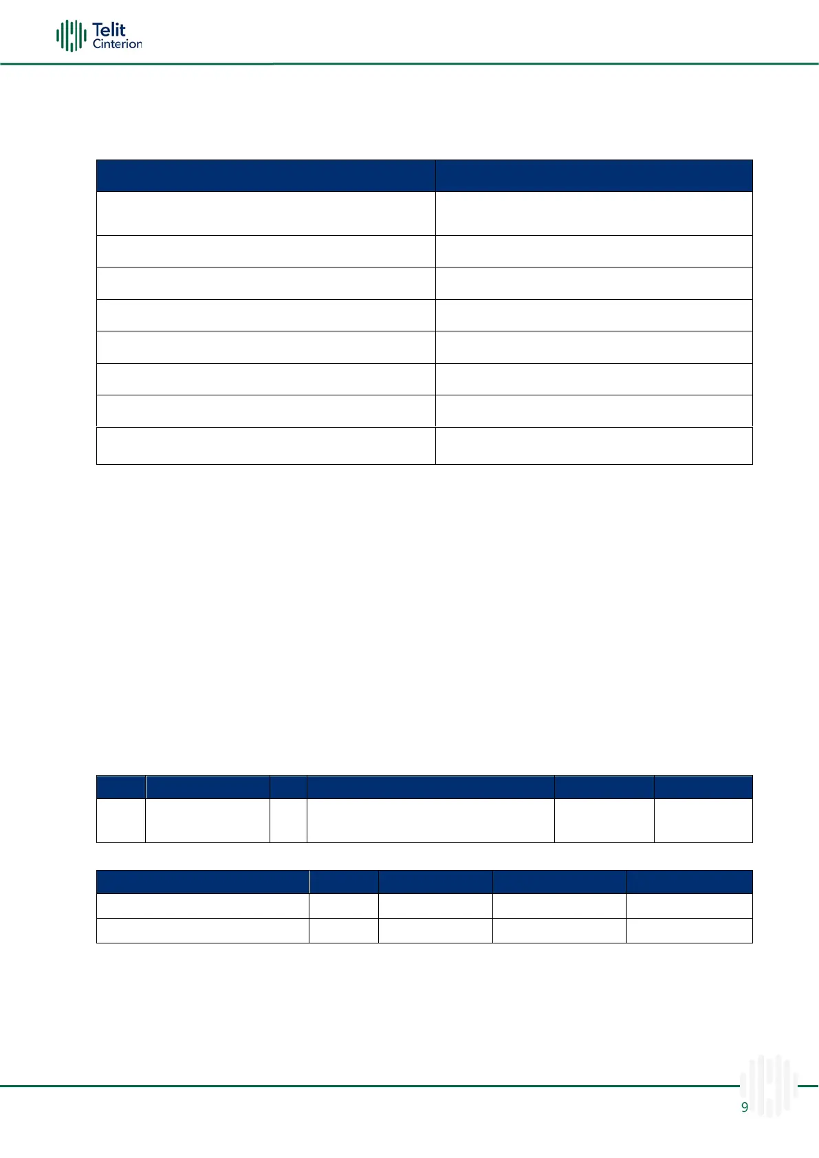
The below table summarizes all the hardware interfaces of the FN990 Family module.
Table 28: FN990 Family Hardware Interfaces
Peripheral Component Interconnect Express Gen
3.0
x2 dual voltage each (1.8V / 2.95V)
W_DISABLE_N, WAKE_ON_WAN_N, LED, DPR
Host Interface
Note: FN990 M.2 data card supports USB 3.1 Gen 2 and PCIe Gen 3 respectively.
Host Interface Switch Function
This section describes the host interface switch functions.
Note: The meaning of the name USB/PCIe switch implies which interface provides
the main function.
Please refer to the 1VV0301750, FN990 Family Software User Guide, regarding each
function.
Table 29:Host Interface Switch Pin
Table 30: USB/PCle Switch Pin
FN990 Family M.2 Card determines the host interface by checking the status of the
USB_PCIE_SWITCH pin at the beginning of the power-on sequences.
* Note: When using PCIe EP, PCIe RC cannot be used, and basic functions such as
mobile data and AT commands are provided through PCIe EP, while USB is provided
only for debugging and specific purpose.

 Loading...