For more details, please refer to the 1VV0301750, FN990 Family Software User
Guide.
* *Note: FN990 Family supports the following devices as EP for data interface:
•
Marvell AQC107 Ethernet Controller
•
Realtek RTL8125 Ehternet Controller
Please consult Telit if a different EP device is used as a data interface since the EP
device kernel driver needs to be modified to use the FN990 network hardware
accelerator.
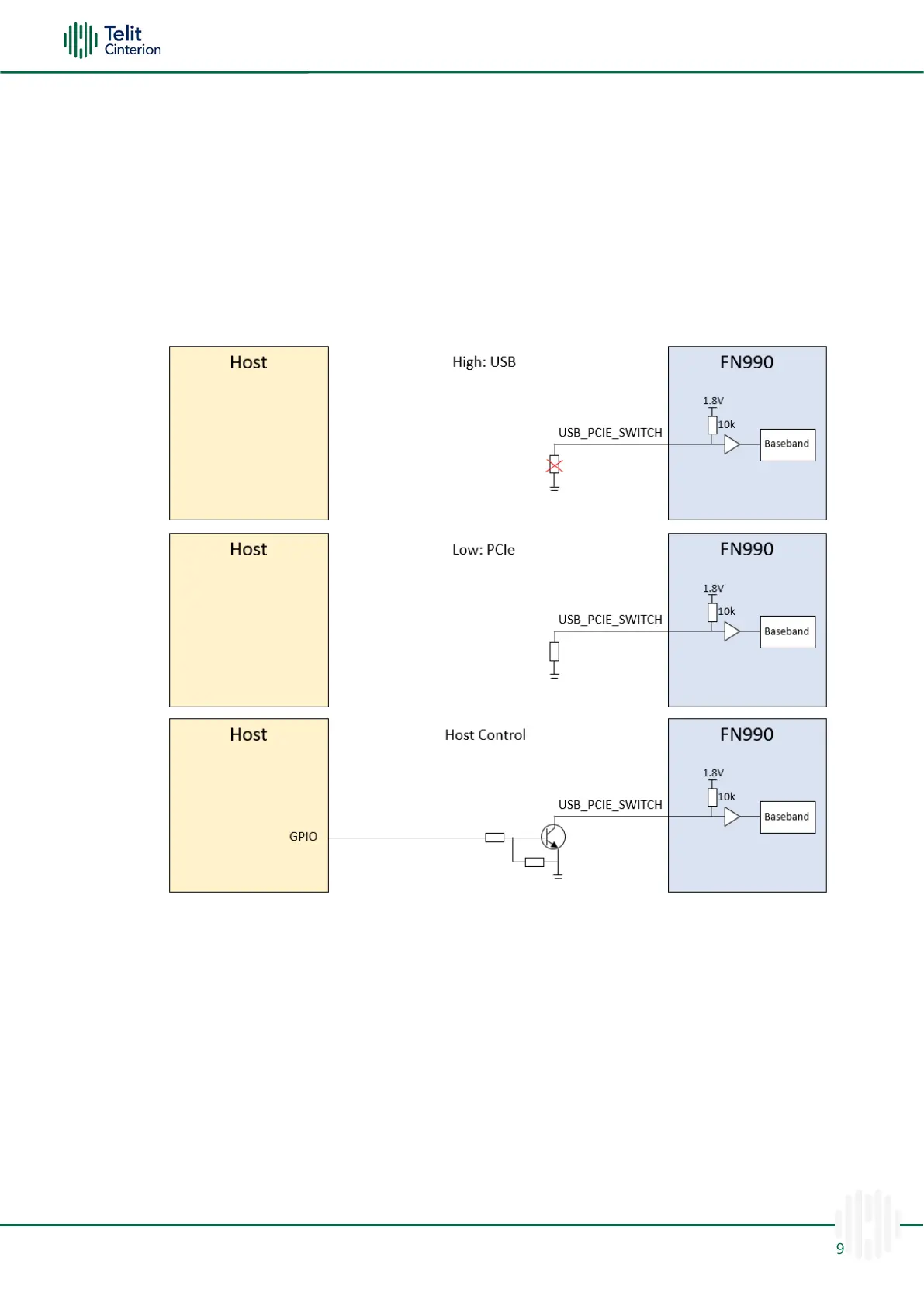
Figure 11: Example Circuit for HOST Interface Switch Function
PCIe Interface
The FN990 Family module includes a PCIe interface. PCIe needs AC coupling series
capacitors on the TX lines in both directions. To interface PCIe with the application board
that controls the modem, 0.22 uF capacitors should be installed on PCIE_RX_P/M lines of
the FN990. The series capacitors are already placed on PCIE_TX_P/M lines inside the
FN990.
Internally, the VPH_PWR level 10k pull-up resistor is already mounted on PCIE_WAKE_N,
PCIE_CLKREQ_N, and PCIE_RESET_N.
The suggested PCIe interface connection is shown in the diagram below:

 Loading...