EasyManuals Logo

Telit Wireless Solutions FN990 Series Hardware Design Guide

Telit Wireless Solutions FN990 Series
83 pages
To Next Page IconTo Next Page
To Previous Page IconTo Previous Page
Page #41 background imageLoading...
Page #41 background image
FN990 Family Hardware Design Guide
1VV0301752 8
Page 41 of 83
2024-05-29
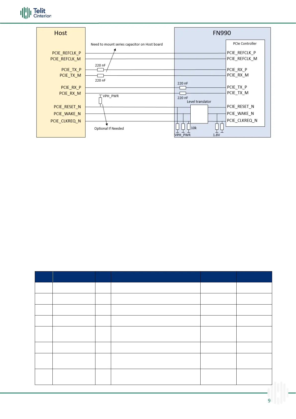
Figure 12: Connection for PCIe Interface
Note: FN990 Family supports PCIe root complex (RC) mode.
Depending on the EP device such as NIC or something else, may require a suitable
value of pull-up resistor on the PCIE_RESET_N line.
Customers interested in using PCIe RC mode can contact Telit Technical Support at:
TS-EMEA@telit.com
TS-AMERICAS@telit.com
TS-APAC@telit.com
Note: The PCIe signals traces must be routed carefully: minimize trace lengths,
number of vias, and capacitive loading. The impedance value should be as close as
possible to the 85 Ohm differential.
Table 31: PCIe Interface Signals
Pin
Signal
I/O
Function
Type
Comment
41
PCIE_TX0_M
O
PCIe transmit 0 Minus
Analog
43
PCIE_TX0_P
O
PCIe transmit 0 Plus
Analog
47
PCIE_RX0_M
I
PCIe receive 0 Minus
Analog
49
PCIE_RX0_P
I
PCIe receive 0 Plus
Analog
53
PCIE_REFCLK_M
I
PCIe differential reference clock
Minus
Analog
55
PCIE_REFCLK_P
I
PCIe differential reference clock Plus
Analog
50
PCIE_RESET_N
I
Functional reset to PCIe bus
VPH_PWR
Internal 10k
PU
52
PCIE_CLKREQ_N
O
PCIe reference clock request signal
VPH_PWR
Internal 10k
PU

Other manuals for Telit Wireless Solutions FN990 Series

Questions and Answers:

Question and Answer IconNeed help?

Do you have a question about the Telit Wireless Solutions FN990 Series and is the answer not in the manual?

Telit Wireless Solutions FN990 Series Specifications

General IconGeneral
BrandTelit Wireless Solutions
ModelFN990 Series
CategoryComputer Hardware
LanguageEnglish