USB OTG Feature
FN990 family supports USB On-The-Go (OTG) function.
Note: Since the FN990 family does not support a USB_ID pin, a TPGIO pin should
be set as the purpose of USB_ID using the #OTGCFG command. The module will
be in host mode if the TGPIO pin is connected to the ground. External 5 V power is
required on an application board to supply 5 V power to the OTG device because
the FN990 family does not supply power for the OTG device.
USB Layout Guidelines
•
If third-party components are required for signal improvement, place them
closer to the USB connector.
•
There are relatively fast edge rates, so must be routed away from sensitive
circuits and signals (RF, audio, and XO).
•
Maintain good isolation between the USB connector and RF antennas
(especially 2.4 GHz).
•
Route the RF signals operating at a 2.4 GHz frequency with the highest
isolation possible from USB_SS_TX/RX traces.
•
USB SS Tx AC coupling capacitors are better placed close to the source or
the ESD/connector side to keep good SI of the main route on the PCB.
•
Route differential pairs in the inner layers with a solid GND reference to
have good impedance control and to minimize discontinuities.
•
Keep isolation between the Tx pair, Rx pair, and DP/DM to avoid crosstalk.
•
The SS-USB Tx and Rx differential pair maximum length is recommended to
be less than 136 mm.
•
For USB 2.0 signal, the maximum trace length should be less than 234 mm.
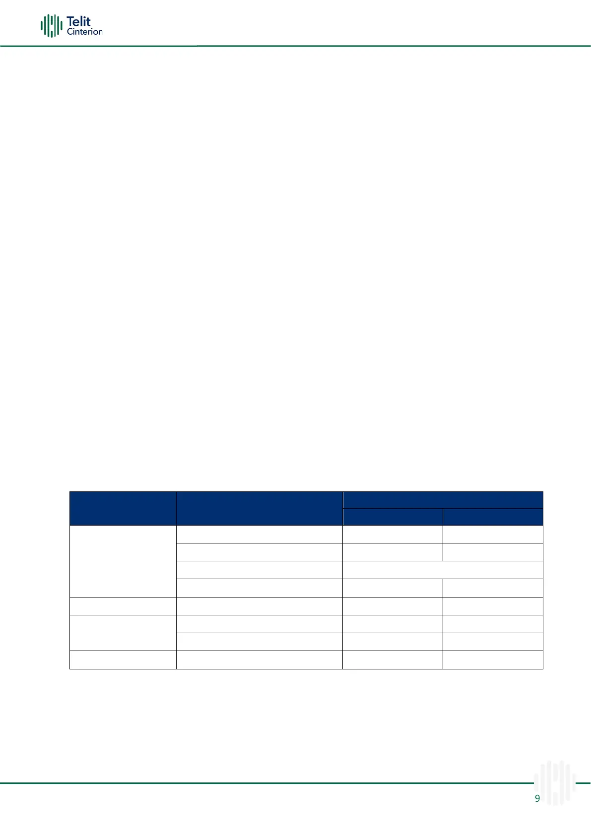
Table 34:USB Routing Constraints
SIM Interface
The FN990 modem family supports an external SIM interface. (1.8 V or 2.95 V)
Note: UIM2 can be assigned as an optional eSIM. In that case, UIM2 can’t be used
as an external SIM interface.

 Loading...