FN990 Family Hardware Design Guide
Table 35: SIM Interface Signals
Supply output for an external UIM1 card
Data connection with an external UIM1
card
Clock output to an external UIM1 card
Reset output to an external UIM1 card
Internal 100k
PU
Active High*
Supply output for an external UIM2 card
Data connection with an external UIM2
card
Clock output to an external UIM2 card
Reset output to an external UIM2 card
Internal 100k
PU
Active High*
Note: * From xx3 official SW, the default UIM_PRESENT pin setting has been
changed from low to high to comply with the M.2 specification standard.
Pin settings can be changed through AT#SIMINCFG, please refer to the AT
commands reference guide for details.
If you have any special requirements, please contact Technical Support or Sales.
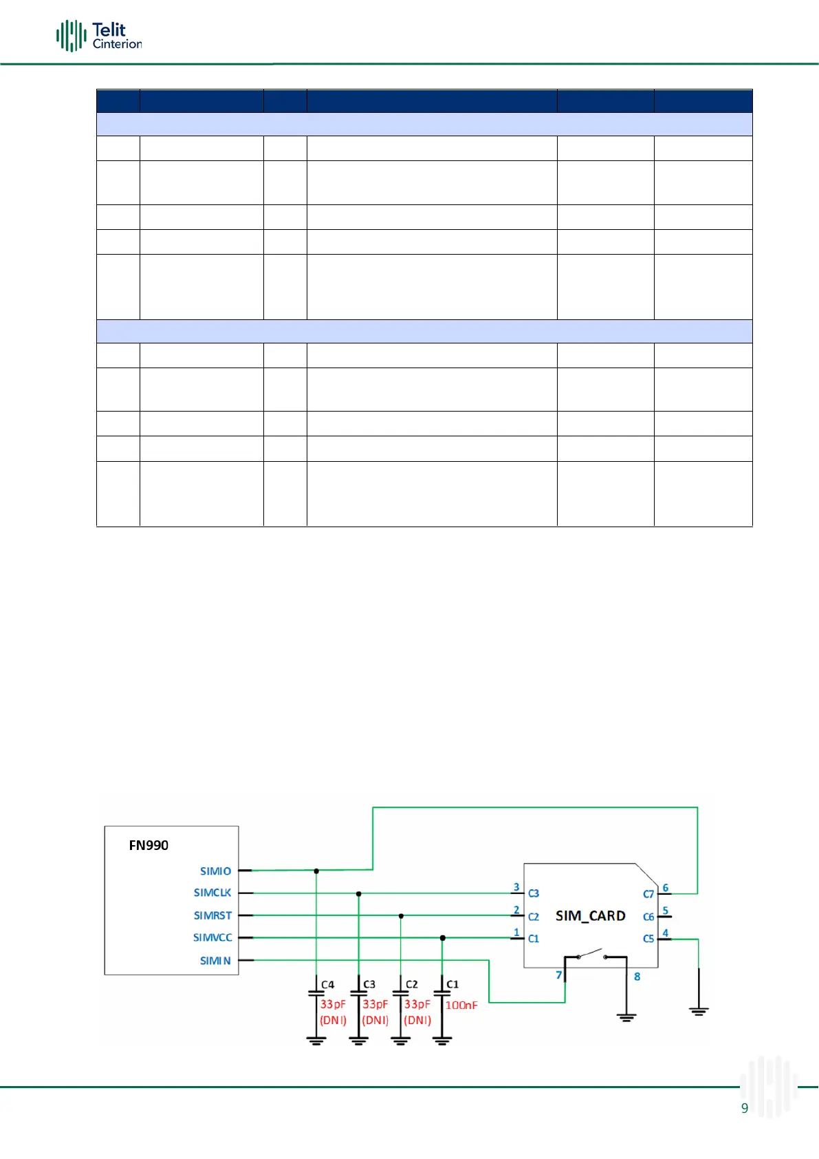
SIM Schematic Example
The diagram below shows in particular how the SIM part of the application interface
should be designed.
Figure 14: SIM Schematic Example

 Loading...