EasyManuals Logo

Telit Wireless Solutions FN990 Series Hardware Design Guide

Telit Wireless Solutions FN990 Series
83 pages
To Next Page IconTo Next Page
To Previous Page IconTo Previous Page
Page #49 background imageLoading...
Page #49 background image
FN990 Family Hardware Design Guide
1VV0301752 8
Page 49 of 83
2024-05-29
Pin
Signal
I/O
Function
Type
Comment
Can be I2S_WS
56
I2C_SDA
I/O
I2C Data
Can be TGPIO_09
1.8V
Internal 2.2k
PU
58
I2C_SCL
I/O
I2C Clock
Can be TGPIO_10
1.8V
Internal 2.2k
PU
Using a GPIO as INPUT
GPIO pins, when used as inputs, can be tied to a digital output of another device and
report its status, provided the device interface levels are compatible with the GPIO 1.8V
CMOS levels.
If a digital output of a device is tied to GPIO input, the pin has interface levels different
than 1.8V CMOS. It can be buffered with an open collector transistor with a 47K ohm pull-
up resistor to 1.8V.
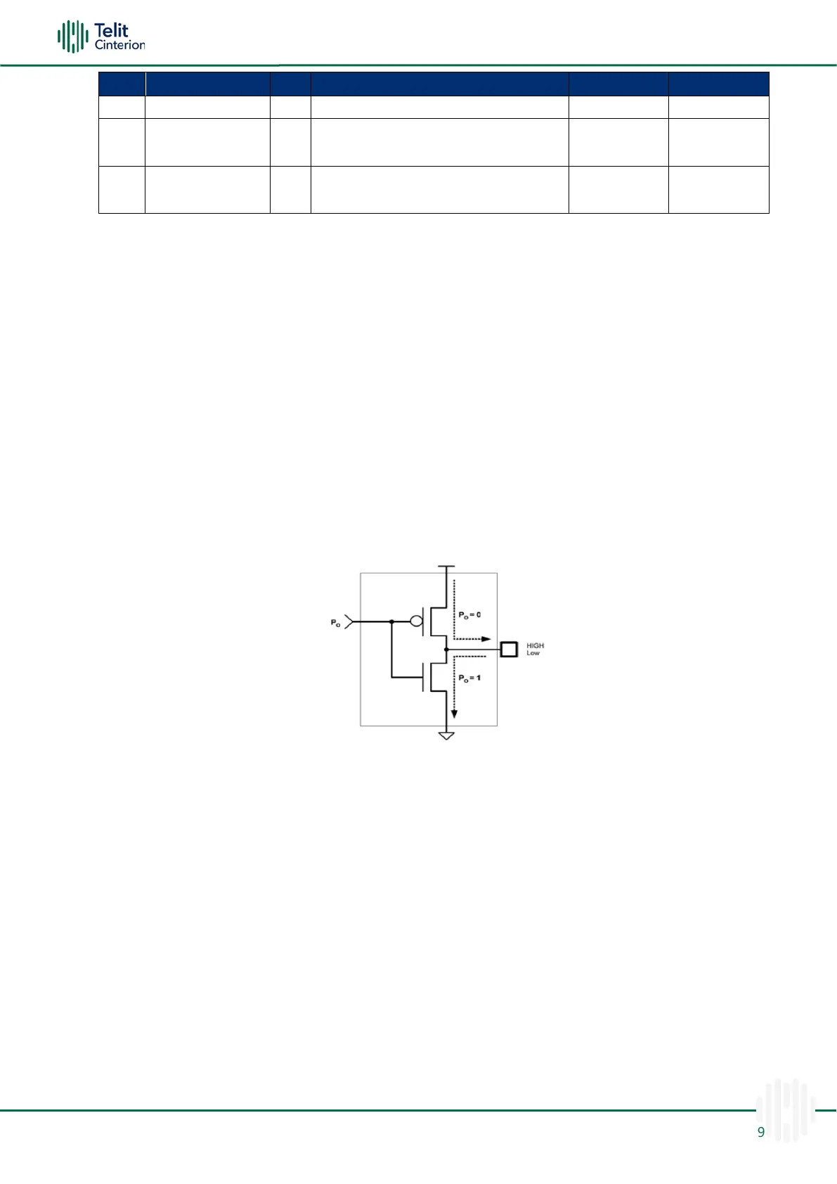
Using a GPIO as OUTPUT
GPIO pins, when used as output, can drive 1.8V CMOS digital devices or compatible
hardware. When set as outputs, the pins have a push-pull output, and therefore the pull-
up resistor can be omitted.
Figure 18: GPIO Output Pin Equivalent Circuit

Other manuals for Telit Wireless Solutions FN990 Series

Questions and Answers:

Question and Answer IconNeed help?

Do you have a question about the Telit Wireless Solutions FN990 Series and is the answer not in the manual?

Telit Wireless Solutions FN990 Series Specifications

General IconGeneral
BrandTelit Wireless Solutions
ModelFN990 Series
CategoryComputer Hardware
LanguageEnglish