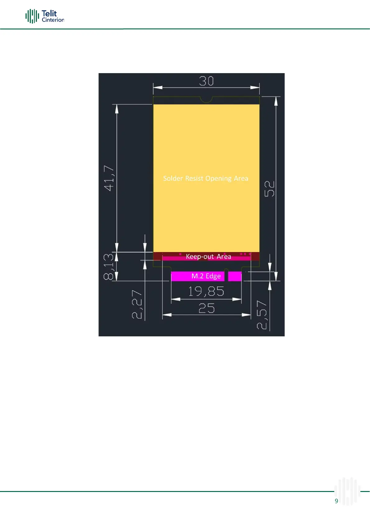
9.4 Solder Resist Opening Area and Keepout Area
The figure below shows the solder resist opening area and keep-out area location on the
FN990 bottom side.
Figure 23: Solder Resist Opening Area and Keep Out Area on Bottom Side
To guarantee the performance and longevity of the end product, the heat generated by
the FN990 module must be dissipated.
A large solder-resist opening area (30*41.7 mm) is provided on the bottom of the FN990
modems for better heat dissipation. The addition of a TIM on the back of the FN990 Family
is the most important factor from the thermal dissipation point of view.
The recommended TIM size is 29 x 38 x 1.5 mm.
Note: For more information on thermal design, refer to the FN990 Family Thermal
Design Guide.
Warning: The keep-out area (30*2.27 mm) on the bottom side is only for
debugging purposes. Please do not use this area for hardware design.

 Loading...