practice section
816047/826047
A
2.
application
2.01 The
6047
and
6047
A 4Wire-to-4Wire SF-to-
E&M
Network
Terminating Modules are each de-
signed
to
interface a
4wire
SF transmission facility
with a
4wire
E&M
trunk
or
line associated with a
two-way dial/supervisory
telephone
circuil. These
modules
combine
the
functions of a
4wire
line
amplifier, an SF transceiver, an SF-to-E&M signal-
ing converter, and a
4wire
pad/transformer mod-
ule. Thus,
the
6047
and
6047
A are
complete
4wire
E&M
SF
signaling and terminating circuits, less
power
and ringing, on single Type 10 modules.
As
such, each module provides full-duplex signaling
conversion and transmission interface between
the
4wire
SF facility and
the
4wire
E&M
trunk
or
line.
The two modules differ only through the presence
of
loopback
circuitry
on
the
6047
A that allows test-
ing of both
the
module and
the
facility from a local
or remote location.
2.02 The
6047
and
6047
A are well suited to a
variety of 4wire-to-4wire SF-to-E&M applications,
both network-terminating and otherwise.
In
network-
terminating applications where
the
serving tele-
phone company uses SF signaling, each module
fulfills Registered Facility Interface Codes
TC31
E,
TC31M, TC32E, TC32M, TL31E, TL31M, TL32E, and
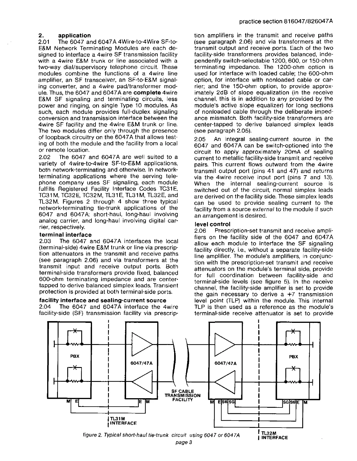
TL32M. Figures 2 through 4
show
three
typical
network-terminating tie-trunk applications of the
6047
and 6047A: short-haul, long-haul involving
analog carrier, and long-haul involving digital car-
rier, respectively.
terminal
interface
2.03 The
6047
and
6047
A interfaces
the
local
(terminal-side)
4wire
E&M
trunk
or
line via prescrip-
tion
attenuators
in
the
transmit and receive paths
(see paragraph 2.06) and via transformers at the
transmit input and receive output ports. Both
terminal-side transformers provide fixed, balanced
600-ohm
terminating impedance and are center-
tapped
to
derive balanced simplex leads. Transient
protection is provided at both terminal-side ports.
facility
interface
and
sealing-current
source
2.04 The
6047
and
6047A
interface
the
4wire
facility-side (SF) transmission facility via prescrip-
tion amplifiers
in
the
transmit and receive paths
(see paragraph 2.06) and via transformers at
the
transmit
output
and receive ports. Each of the
two
facility-side transformers provides balanced, inde-
pendently switch-selectable 1200, 600,
or
150-ohm
terminating impedance. The 1200-ohm option is
used for interface with loaded cable;
the
600-ohm
option, for interface with nonloaded cable
or
car-
rier; and
the
150-ohm option,
to
provide approx-
imately
2dB
of slope equalization (in
the
receive
channel,
this
is in addition to any provided
by
the
module's active slope equalizer) for long sections
of nonloaded cable through
the
deliberate imped-
ance mismatch. Both facility-side transformers are
center-tapped
to
derive balanced simplex leads
(see paragraph 2.05).
2.05
An
integral sealing-current source in the
6047
and
6047A
can be switch-optioned into
the
circuit
to
apply approximately
20mA
of sealing
current
to
metallic facility-side
transmit
and receive
pairs. This
current
flows outward from
the
4wire
transmit
output
port (pins
41
and 47) and returns
via
the
4wire
receive input port (pins 7 and
13).
When the internal sealing-current source is
switched out of
the
circuit, normal simplex leads
are
derived on
the
facility side. These simplex leads
can be used to provide sealing
current
to
the
facility from a source
external
to
the
module if such
an arrangement is desired.
level
control
2.06 Prescription-set transmit and receive ampli-
fiers on
the
facility side of
the
6047
and
6047A
allow each module to interface
the
SF signaling
facility directly,
i.e.,
without
a separate facility-side
line amplifier. The module's amplifiers, in conjunc-
tion with
the
prescription-set
transmit
and receive
attenuators on
the
module's terminal side, provide
for full coordination between facility-side and
terminal-side levels (see figure
5).
In
the
receive
channel,
the
facility-side amplifier is set to provide
the
gain necessary
to
derive a
+7
transmission
level point
(TLP)
within
the
module. This internal
TLP is then used as a reference as the module's
terminal-side receive
attenuator
is set
to
provide
, TL32M
I
INTERFACE
I
I
11
~
I
! I
/
I
I
I
PBX
6047/47A
I
I
n/
I
I
~
I
I
BlE
ISSION
I
lTV
M E
SBISGI
I
ISGI
SB
E M
i
I
SFCA
TllANSM
FACll
E M
6047/47A
ITL31M
,INTERFACE
figure
2.
Typical short-haul tie-trunk circuit using 6047
or
6047A
page 3
M E
PBX



 To Next Page
 Loading...