421 01 9220 00 10/01/12
INSTALLATION INSTRUCTIONS
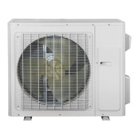
R−410A Ductless Split System
Air Conditioner and Heat Pump
MODELS: DLC4(A/H)−Outdoor, DLF4(A/H)−Indoor
SIZES: 9K, 12K, 18K, 24K, 30K, and 36K
NOTE: Read the entire instruction manual before starting the installation.
TABLE OF CONTENTS
PAGE
PARTS LIST 1.......................................
SAFETY CONSIDERATIONS 1........................
GENERAL 2.........................................
SYSTEM REQUIREMENTS 2..........................
ELECTRICAL TABLES 2..............................
DIMENSIONS 3......................................
CLEARANCES 7.....................................
INSTALLATION 8....................................
INDOOR UNIT INSTALLATION 8.......................
Install Mounting Plate 8...........................
Drill Hole in Wall for Connecting Piping,Drain&Wiring. .9
OUTDOOR UNIT INSTALLATION 9.....................
Piping and Drainage Connections 9.................
Control and Power Wiring from Outdoor Unit 10......
AIR PURGING AND LEAKAGE TEST 11................
START−UP 12.......................................
OPERATION TEST 12................................
AIR FILTER INSTALLATION 12........................
CONNECTION DIAGRAMS 13.........................
TROUBLESHOOTING 14.............................
The following parts are included in your indoor unit. Please
contact your dealer if any parts are damaged or missing.
Parts Qty.
Mounting Plate 1
Remote Control 1
Remote Control Holder 1
Mounting Hardware 7
Battery (1.5V) 2
SAFETY CONSIDERATIONS
Installing, starting up, and servicing air−conditioning
equipment can be hazardous due to system pressures,
electrical components, and equipment location (roofs,
elevated structures, etc.).
Only trained, qualified installers and service mechanics
should install, start−up, and service this equipment.
Untrained personnel can perform basic maintenance
functions such as cleaning coils. All other operations should
be performed by trained service personnel.
When working on the equipment, observe precautions in the
literature and on tags, stickers, and labels attached to the
equipment.
Follow all safety codes. Wear safety glasses and work
gloves. Keep quenching cloth and fire extinguisher nearby
when brazing. Use care in handling, rigging, and setting
bulky equipment.
Read these instructions thoroughly and follow all warnings
or cautions included in literature and attached to the unit.
Consult local building codes and National Electrical Code
(NEC) for special requirements. In Canada, refer to current
editions of the Canadian Electrical Code, CSA 22.1.
Recognize safety information. This is the safety−alert
symbol
!
!
. When you see this symbol on the unit and in
instructions or manuals, be alert to the potential for personal
injury.Understand these signal words: DANGER,
WARNING, and CAUTION. These words are used with the
safety−alert symbol. DANGER identifies the most serious
hazards which will result in severe personal injury or death.
WARNING signifies hazards which could result in personal
injury or death. CAUTION is used to identify unsafe
practices which may result in minor personal injury or
product and property damage. NOTE is used to highlight
suggestions which will result in enhanced installation,
reliability, or operation.
!
WARNING
ELECTRICAL SHOCK HAZARD
Failure to follow this warning could result in personal
injury or death.
Before installing, modifying, or servicing system, main
electrical disconnect switch must be in the OFF
position. There may be more than 1 disconnect switch.
Lock out and tag switch with a suitable warning label.
CAUTION
!
EQUIPMENT DAMAGE HAZARD
Failure to follow this caution may result in equipment
damage or improper operation.
Do not bury more than 36 in. (914 mm) of refrigerant
pipe in the ground. If any section of pipe is buried, there
must be a 6 in. (152 mm) vertical rise to the valve
connections on the outdoor units. If more than the
recommended length is buried, refrigerant may migrate
to the cooler buried section during extended periods of
system shutdown. This causes refrigerant slugging and
could possibly damage the compressor at start−up.