F96CTN and G96CTN (Series A): Installation, Start-up, Operating, Service and Maintenance Instructions
Manufacturer reserves the right to change, at any time, specifications and designs without notice and without obligations.
43
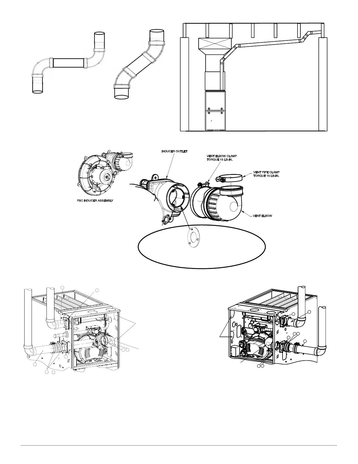
A14546
Fig. 52 – Near Furnace Vent Connections
A170006
Fig. 53 – Inducer Vent Elbow
A11309A
UPFLOW LEFT CONFIGURATION
A11308A
UPFLOW RIGHT CONFIGURATION
Avoid short horizontal offsets with 90
deg. Elbow s. Short off set s can be
difficult to slope and may trap con-
densate.
Use 45 deg. Elbows where
possible, to ensure conden-
sate drainage.
Slope vent pipe back to the
furnace at least ¼” per foot
7$%6217+(,1'8&(5287/(75(675,&72561$3
,1727+(6/276$77+(287/(72)7+(,1'8&(5
)2586$*(
6((0$;,080(48,9$/(179(17/(1*7+7$%/(
)702)9(1725/(6621/<
1
2
3
4
6
7
5
5
Rotate vent elbow to
required position.
Any other unused
knockout may be used
for combustion air
connection.
&
1
2
3
4
5
6
7
5
Rotate vent elbow to
required position.
Any other unused
knockout may be used
for combustion air
connection.